Sheet Metal & Press Brake plans and checks how a Fusion sheet-metal part is bent on your press brake, and writes its shop files. It also matches the flat pattern to your brake, and makes forms, tab and slot joints and the punch-press files.
The commands are in the Press Brake panel of the Sheet Metal tab (Design workspace): Bend Sheet, Apply Bend Rule, Create Form and Tab and Slot as buttons, all ten in the panel's menu. The i button at the bottom left of every dialog opens this guide. A free trial starts the first time you open a command (License and trial). New to the add-in? Start with Getting started.
Getting started#
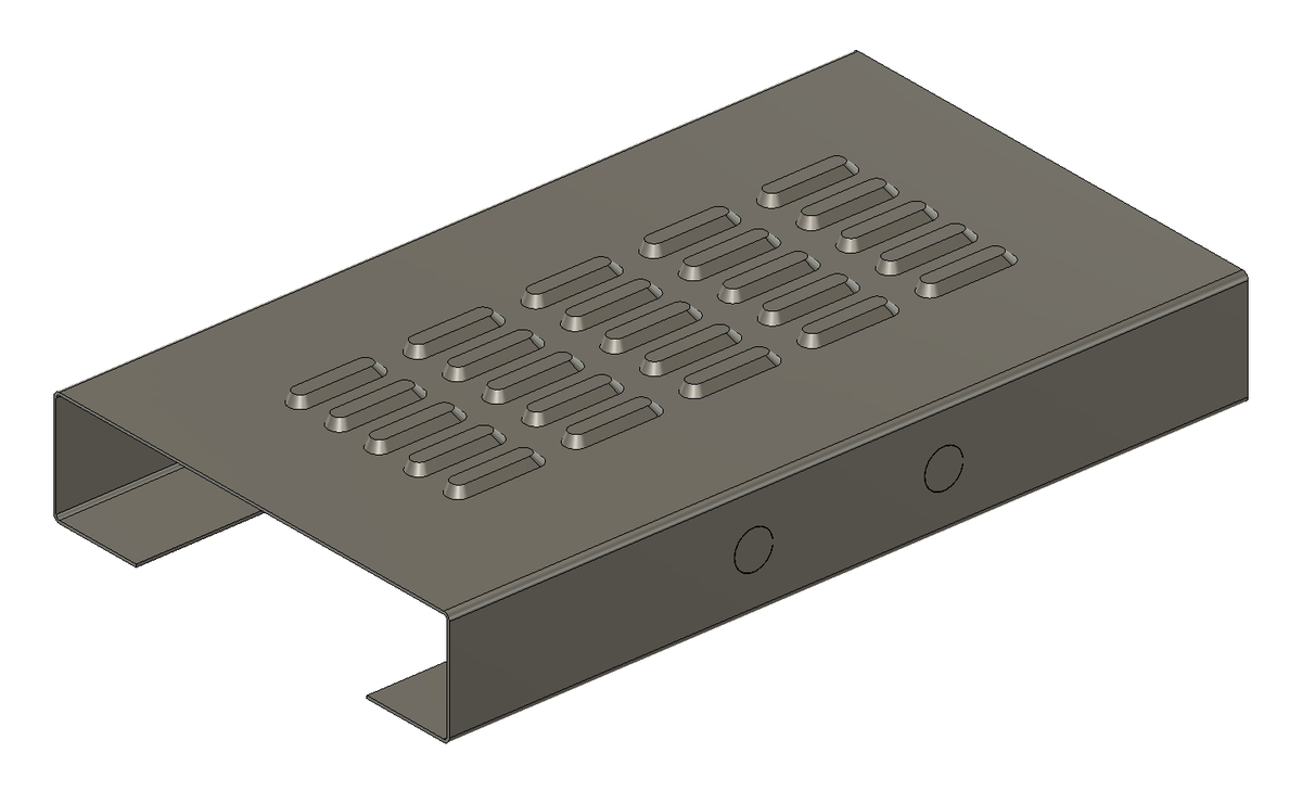
Your first part from the model to the shop files, step by step. Steps 2 to 4 set up your press brake once; steps 5 to 9 are what you do for every part. The pictures follow one example part, a 1.5 mm steel cover with four bends, two knockouts and 25 louvers, on a TRUMPF TruBend 5085 with UKB tools: use your own part, machine and tools.
- You need a sheet-metal part in a Part or Hybrid design that captures design history. A STEP import is a plain solid: convert it first with Fusion's Convert to Sheet Metal. No flat pattern yet? Bend Sheet and Create Form make one.
- To try the add-in before setting up your shop, skip steps 2 to 4: the commands then use the starter library, and Bend Sheet says so in an orange line.
- Steps 6 and 7 are only for parts with forms (louvers, knockouts, dimples ...).
1. Find the commands#

Open the Sheet Metal tab of the Design workspace. The Press Brake panel shows Bend Sheet, Apply Bend Rule, Create Form and Tab and Slot; the arrow under the panel opens its menu with all ten commands (The ten commands). The free trial starts the first time you open a command. The i button at the bottom left of every dialog opens this guide.
2. Add your press brake#
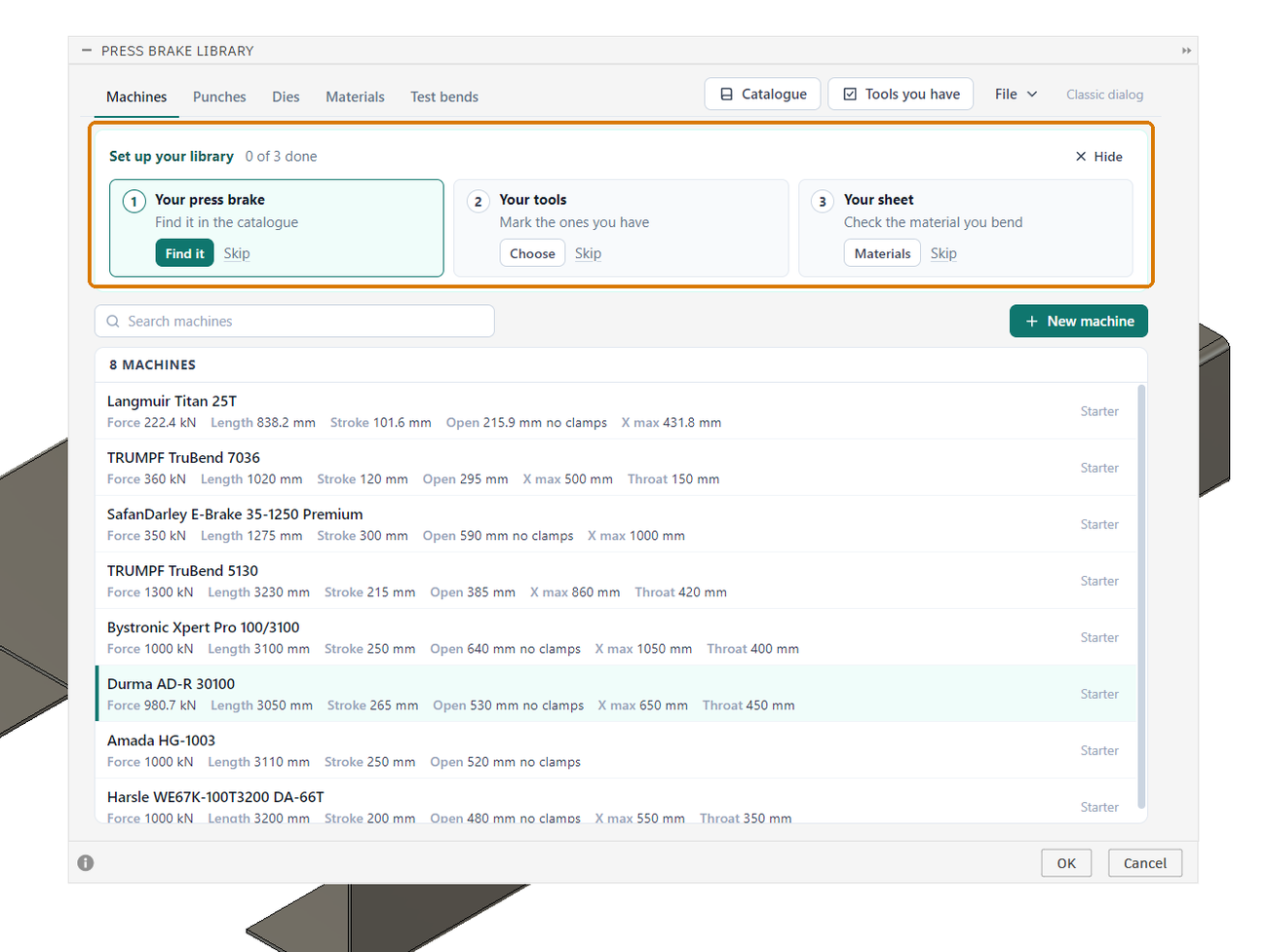
- Open Press Brake Library from the panel's menu. On its first opening, Set up your library sits above the lists with three steps: your press brake, your tools, your sheet.
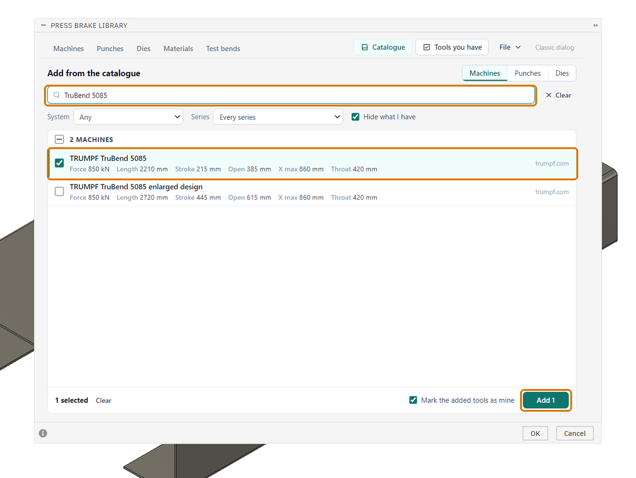
- Click Find it: the Catalogue opens on its machines, more than 400 press brakes from their makers' data.
- Type the model in the search box (
TruBend 5085), tick your machine and click Add. New parts now start on it.
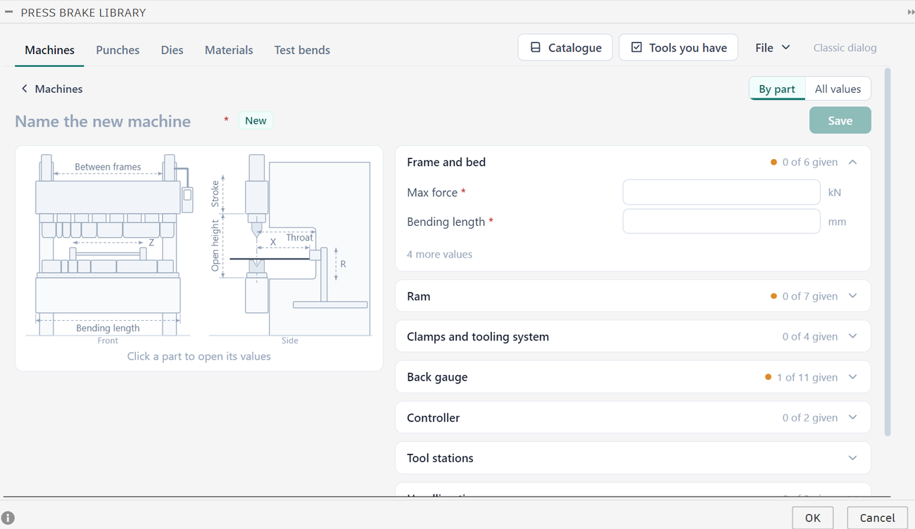
Not in the catalogue? Under Machines, start from a similar one with Save as copy, or click + New machine: Max force and Bending length are enough to start, and each further value turns on more checks (Machine values the checks use).
3. Add your dies and punches#
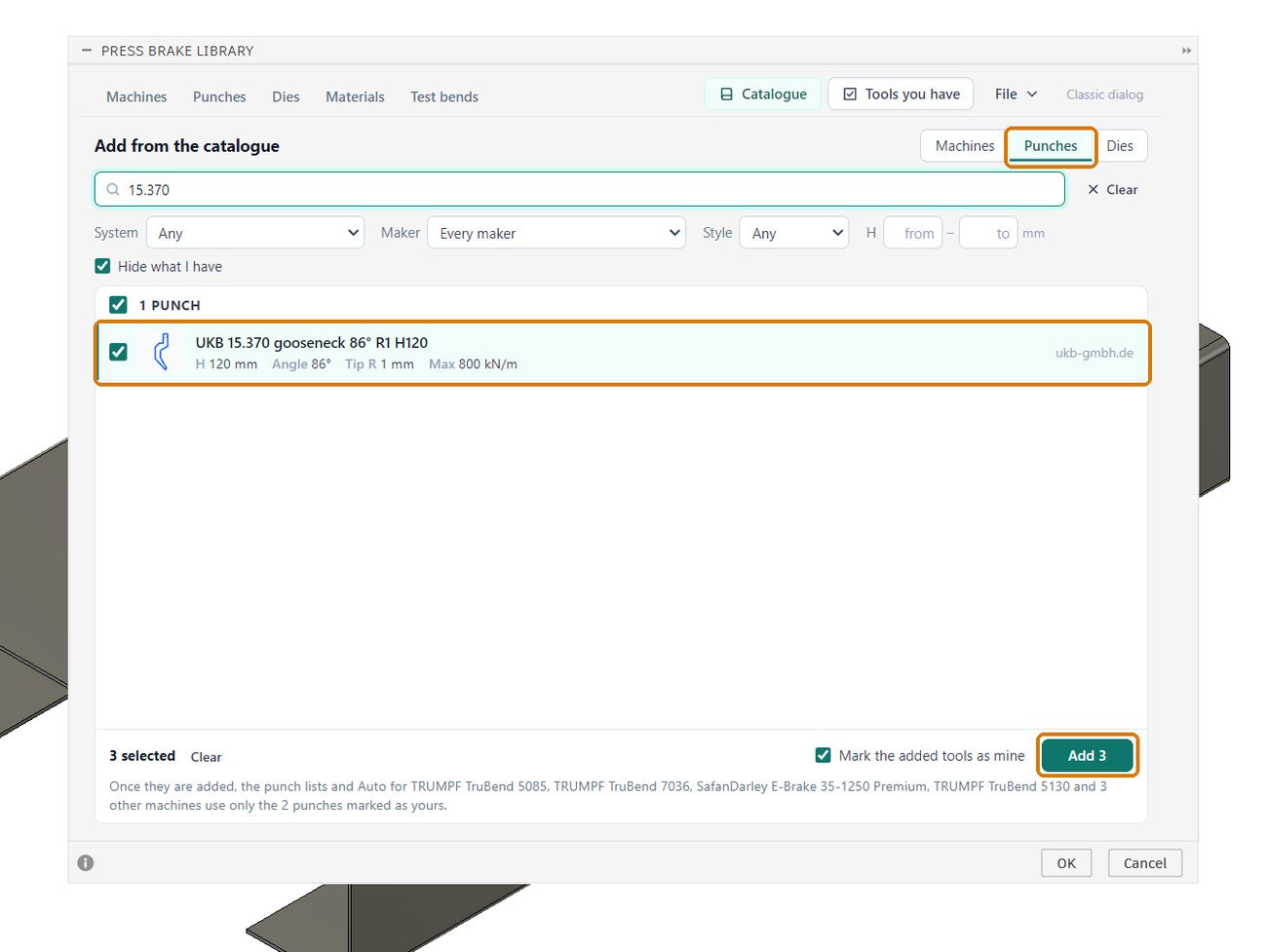
- Still in the catalogue, click Punches, type the part number on the
tool (
15.370) and tick it. Do the same for each punch you have, then for your dies under Dies (29.511). The ticks stay while you search again. - Keep Mark the added tools as mine ticked and click Add.
- Click OK: the library is saved.
On a machine, the die and punch lists and Auto tools + order then offer only the tools marked as yours (the note above Add names the machines), so add every tool you have. A tool that is not in the catalogue: + New punch or + New die, with its height, angle, V opening and the Max force stamped on it (Editing an entry).
4. Check the material#
Click Materials in the library (the third step of Set up your
library). Bend Sheet and Apply Bend Rule take the material from the part's
Fusion material (Steel A1008 gives A1008 CS cold-rolled steel). If
yours is missing, add it with + New material; its K-factor can
stay auto.
5. Match the flat pattern to your brake#
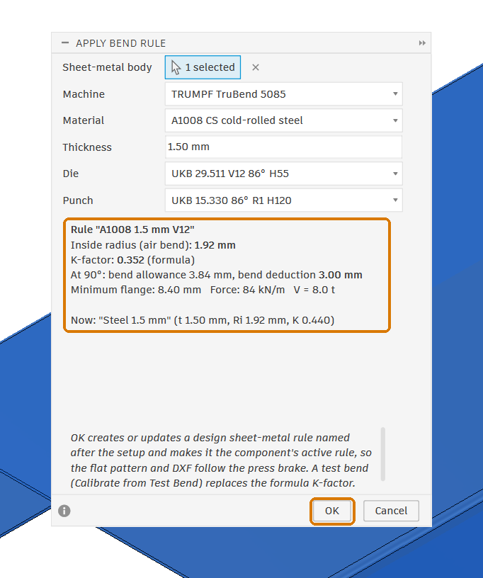
- Select the part and click Apply Bend Rule.
- Check Machine, Material, Thickness, Die and Punch. The dialog shows the rule it will set (the inside radius the die gives, the K-factor, the bend deduction) and the part's rule now.
- Click OK. The part gets the rule (here A1008 1.5 mm V12, inside radius 1.92 mm, K-factor 0.352) and Fusion recomputes the bends and the flat pattern.
Do it before the first blank is cut: the blank is cut from this flat pattern (Apply Bend Rule).
6. Add the forms (parts with forms)#
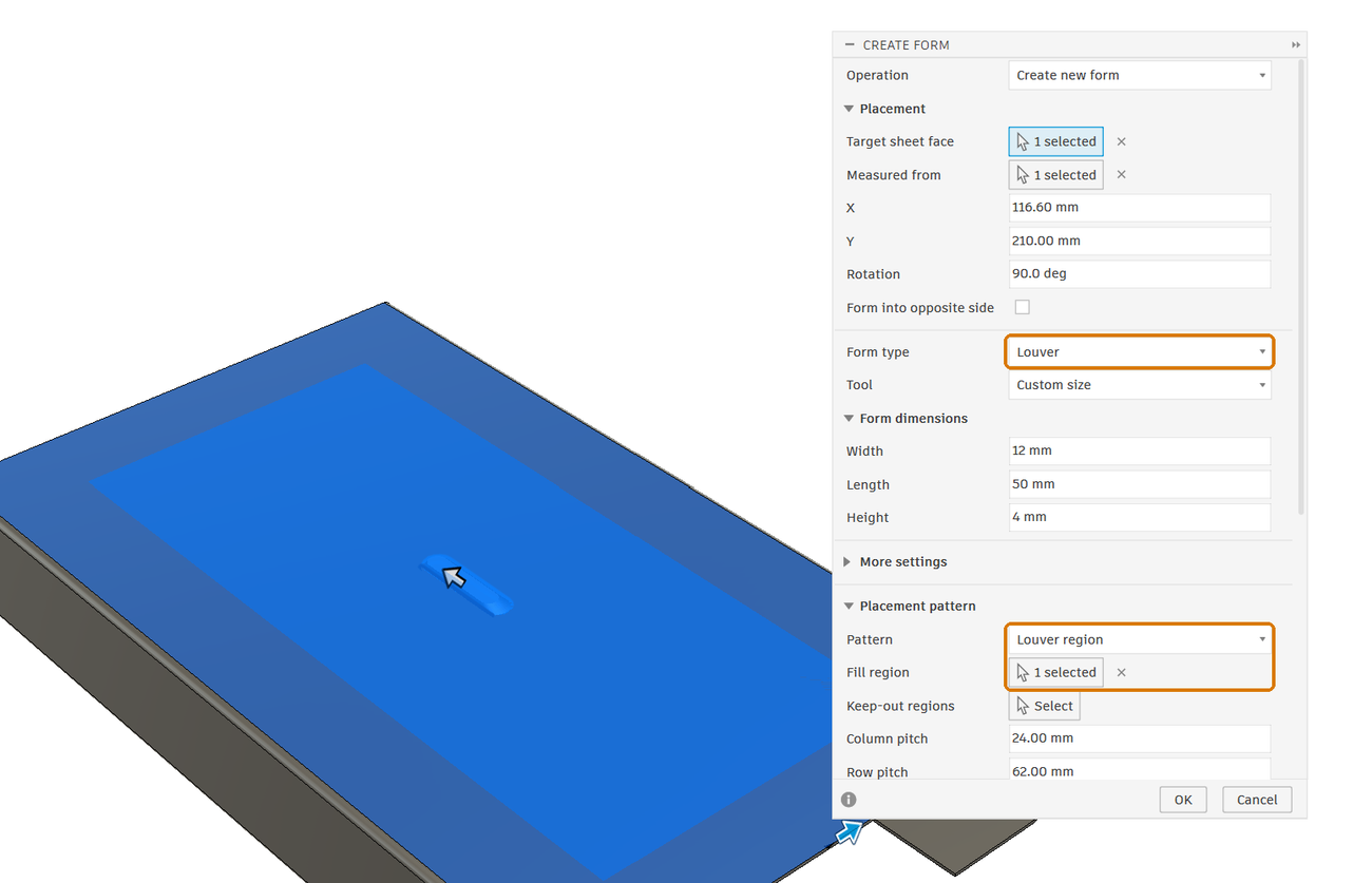
Forms are punched in the flat blank before it is bent, so make them before the bend plan.
- Select the face and click Create Form. Choose the Form type and its sizes; the form is previewed where you clicked.
- For many forms, open Placement pattern: Rectangular, Circular, or Louver region, which fills a closed sketch profile (Fill region) at the Column pitch and Row pitch. The preview shows the first louver; OK fills the region.
- Click OK. The example has two Gland M20 knockouts in a wall, then 25 louvers 12 x 50 mm in the region sketch on the top.
Make the other forms before a louver region: the region keeps clear of the forms already there (Create Form).
7. Write the punch-press files (parts with forms)#
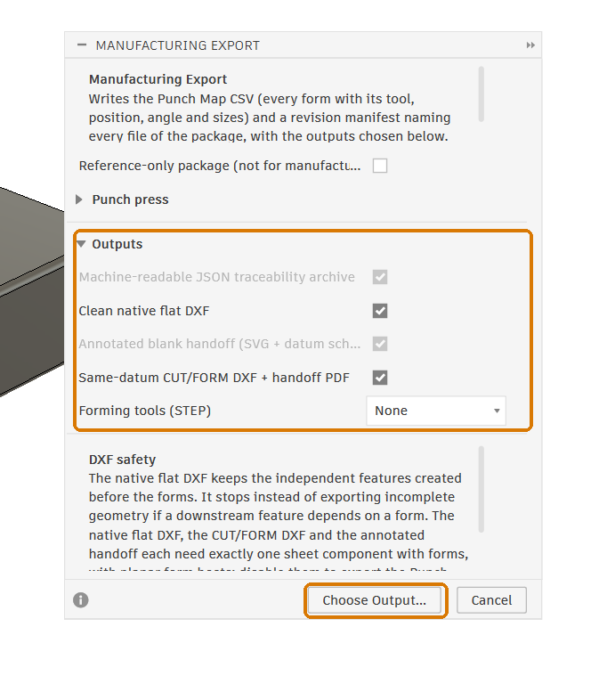
- Optional: run Audit Forms; it lists any form that needs fixing.
- Click Manufacturing Export, keep the Outputs you need ticked (the CUT/FORM DXF + handoff PDF for the punch press) and click Choose Output...
- When a forming tool is not qualified by your shop, the add-in asks first: Yes exports with the reference tool. The closing message lists the files.
Cut and punch the blank from the CUT/FORM DXF and the handoff PDF, never from Bend Sheet's flat DXF, which leaves the forms out (Manufacturing Export).
8. Plan the bends#
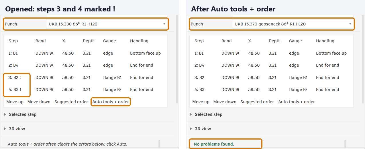
- Click Bend Sheet. It selects the part and plans its bends in a suggested order on your machine, with a die and punch for the thickness (a part with many forms takes a few seconds to read).
- Read the bend table and the Checks under it. A step marked ! has a problem: in the example, the 50 mm return lips meet the straight punch as it lifts out after steps 3 and 4.
- Click Auto tools + order. Auto tries the bend orders with your tools and keeps a plan that every check clears, in 3D too; here it takes the gooseneck punch, in about 20 seconds.
- Optional: open 3D view, tick Show the selected step in 3D and click Play all steps to watch the part on the machine.
No plan is clear? See When a check fails and When Auto finds no plan.
9. Write the shop files#
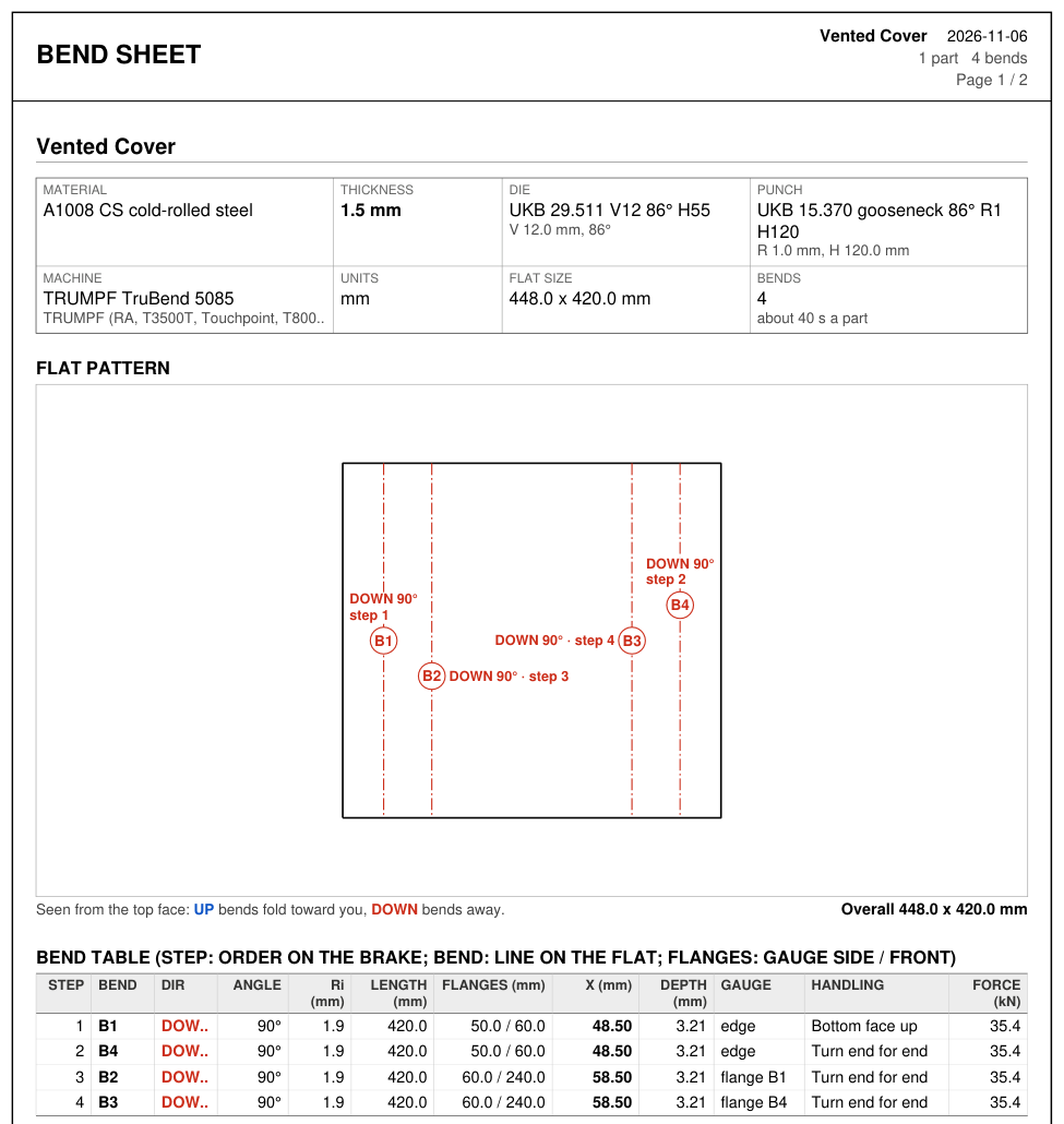
- Under Outputs, keep the files you need ticked. When the part's flat was made with another inside radius or K-factor than its die and punch give, Apply the die's bend rule to the flat first shows there, ticked: OK then sets their rule before writing the files (Fusion recomputes the flat; Undo takes it back). Untick it to keep the flat as it is.
- Click Choose Folder... (the OK button) and choose the folder. The closing message lists the files, the rule applied and the checks.
| File | For |
|---|---|
| Bend sheet PDF | The operator: the setup, the flat pattern with each bend's step, and for every step the back gauge X, the depth, how the part is placed and the tools. |
| Flat DXF | Cutting a part without forms: layers CUT, BEND, ETCH and NOTES. |
| Bend program CSV | The program for the press brake's controller. |
Writing the files keeps the plan with the part (save the design): the next Bend Sheet opens on it (What Bend Sheet keeps).
Next steps#
- Measure a test bend: bend one strip, measure it and run Calibrate from Test Bend. Apply Bend Rule then uses your measured bend deduction instead of the formula.
- Turn every check on: the Checks list the machine values that are not given (table width, back gauge X min ...); enter them in the library (Machine values the checks use), and your controller's coordinates (Your machine's coordinates).
- Exact shapes of your own tools: import a DXF or pick a sketch (Entering an outline); catalogue tools have their makers' outlines already.
- Joints: locating tabs and slots between sheets with Tab and Slot.
- Something stops you? If something goes wrong.
The ten commands#
What each command does; click its name for its section.
| Press brake | What it does |
|---|---|
 Bend Sheet | The bend order, the die, punch and back gauge X of every step, and the checks; writes the shop PDF, the flat DXF and the bend-program CSV. |
 Apply Bend Rule | Sets the part's sheet-metal rule from your material, die and punch, so the flat pattern matches the brake. |
 Calibrate from Test Bend |
Stores the bend deduction and K-factor measured on one bent test strip. |
 Press Brake Library |
Your machines, punches, dies and materials, the tools you have and the test-bend calibrations. |
| Forms and punch press | What it does |
 Create Form | Creates a form, or edits, moves, patterns or deletes one made before. |
 Forming Tool Library |
Your forming tools, with their sizes, tool codes and evidence; Create Form lists the ones that fit. |
 Tab and Slot | Locating tabs and matching slots at a straight 90° joint. |
 Manufacturing Export |
The Punch Map CSV with its revision manifest and, as you choose, the handoff PDF and SVG, the CUT/FORM DXF, Fusion's flat DXF, a JSON and the forming tools as STEP. |
 Audit Forms | Checks the forms' records, references and model state. |
 About Sheet Metal and Press Brake |
The version, price, license, updates and privacy, and Open help. |
Press Brake Library#
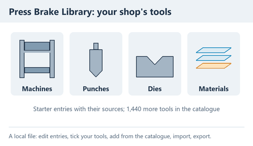
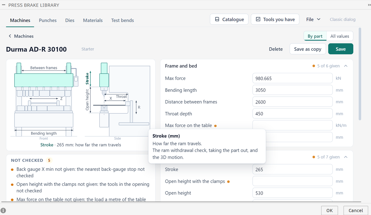
Press Brake Library holds your machines, punches, dies and materials, and the test bends stored by Calibrate from Test Bend. It opens as a page: the tabs Machines, Punches, Dies, Materials and Test bends list the entries, and a row opens its entry. What a box, a button or a mark is for is in its tooltip: hold the pointer on it, or reach it with Tab.
| To | Use | See |
|---|---|---|
| Change, add or delete an entry | Its row in a list, or + New | Editing an entry |
| Tick the tools your shop has | Tools you have, or the I have it switch of a row | The tools you have |
| Add tools or machines from the catalogue | Catalogue | More tools and machines |
| Import or export the library | File | Import, export and the library file |
| Put back the starter entries | File > Restore the starter entries… | Starter library |
| Delete a test bend | Test bends | Import, export and the library file |
Each list has a search box: its words must all be in an entry's name or
notes, without regard to capitals; a size (V16) matches only
whole, so it finds no V160, and V12,5 is V12.5; a style, a
maker or a part number also matches part of a word. The punch and die
lists add Fits (only the tools that fit a machine), Mine
only and a chip for each type or style. While the library file does
not exist yet, Set up your library above the lists offers three
steps, your press brake, your tools and your sheet; each can be skipped,
and Hide hides them for good.
Saving. A change is saved by the button beside it: Save on an entry, Add in the catalogue, Save under Tools you have. Until then it stays on the page while the dialog is open, and a bar at the bottom names what is not saved yet (Not saved yet: 2 "I have it" ticks · 1 catalogue row to add), each a link to it, with Save all. The dialog's OK saves all of it in one write, catalogue rows ticked but not added included, closes, and says what it saved and what it left, with why; it is greyed while an entry typed in cannot be saved (a value missing or wrong), and the bar says so. Cancel closes and drops every change not saved.
The tools you have#
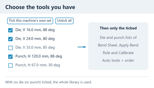
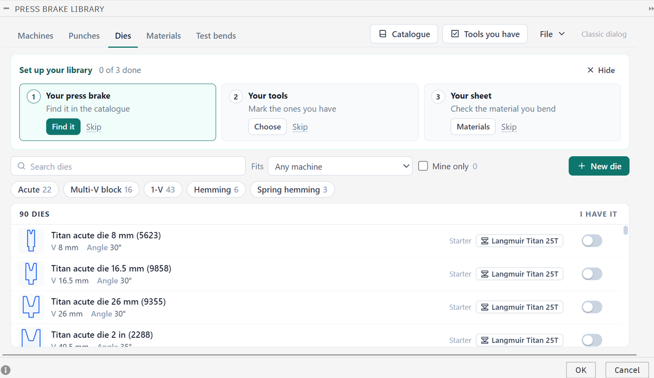
The dies and punches switched on under I have it are the ones the lists and Auto tools + order use. Tools you have shows, for the Machine chosen, every die and punch that fits it, the bending dies, the bending punches and the special tools apart, each with its switch: switch on the ones your shop has. Tick this machine's own set switches on the tools made for it; Untick all, after a question, switches off every tool listed. The search box keeps the tools whose names, notes or values hold all its words; the switches it hides stay as they are. Save, under the table once a switch changed, saves them; so do Save all and OK.
- The switch is the tool's I have this tool: the same tick as the I have it switch of its row in the punch or die list and the one on its entry, under Fits. It says your shop has the tool, so it counts on every machine of the tool's tooling system, not only on the machine chosen; a tool made for one machine counts only on that one, and only its table lists it (Tools made for one machine). Ticks stay until saved, also when you change the machine; the line above the table counts the tools that fit the machine chosen and how many of them its lists use.
- A tool you enter yourself comes ticked, and stays in the lists when you later add tools from the catalogue. When it would be the first ticked tool of its kind on a machine, the lines under its name say so before you save: that machine's lists then use only the ticked ones.
- On each machine, the die lists of Bend Sheet and Apply Bend Rule, the die a new part is given and Auto tools + order take the same dies: those that fit the machine but the ones made for another machine (Tools made for one machine), only your ticked ones when you ticked any. With none ticked, every die that fits is used. A list also shows the die a setup already has. Calibrate from Test Bend lists the ticked dies of the whole library, those of the machine new parts start on first. Punches work the same way.
- The dies and punches you bend with and the special ones (hemming dies, flattening punches, offset tools, dies of type Other) are ticked apart: with only your hemming die ticked, every die you bend with is still used; with bending dies ticked, a hemming die you did not tick is not.
- Before you save a tool or add tools from the catalogue, the lines under the tool's name (in the catalogue, the line above Add) say when that leaves other tools out of a machine's lists (and how many ticked ones they keep), or when the lists leave out the tool itself, each worked out on every machine of your library as its lists are made; they name the machines when it is not all of them (... the die lists and Auto for Durma AD-R 30100 use only the 1 die marked as yours.). The message after the save says it again.
More tools and machines#
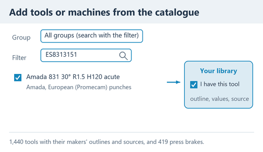
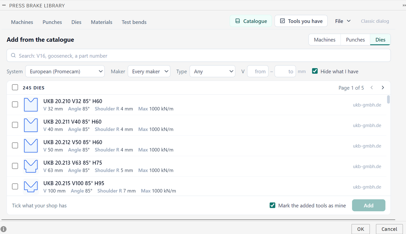
Catalogue, in the page's header, adds 1,440 punches and dies and 419 press brakes beyond the starter library, each with its published values and its source in its notes: UKB, Mate (with its American APS line), WILA (New Standard and American), Wilson Tool American Precision and AMADA AFH tools, and Durma, TRUMPF, Bystronic, AMADA, SafanDarley, LVD, HACO, Baykal and Prima Power press brakes, with their speeds, back gauge travel and controller where the maker prints them (older models a maker no longer lists are in groups of their own). The press brakes come without a clamp drawing: their clamp is the typical one of their tooling system until you give its sizes.
- Choose Machines, Punches or Dies at the top right (opened from a list, the catalogue shows that kind). It opens on the press brakes while your library holds only the starter machines, else on the dies; the tools on the tooling system of the machine new parts start on (System; Any shows every system).
- In the search box, type words the rows' names or notes must all hold: a
size (
V16,H120, matched whole, soV16finds no V160 or V16.1), a style (gooseneck, also part of a word), a part or order number (50221,ES8313151), or another maker's tool that a profile is the same as (Amada 60402, from Mate's cross-reference). Maker (Series for the press brakes), Type or Style, and the size range (a die's V opening, a punch's height, in the document units) narrow them further. The rows come 50 to a page. - Tick the tools or machines your shop has; the box above the rows ticks the whole page, and Clear in the footer unticks every page. Ticks stay while you change the search, the filters or the page. A machine's row gives its force, bending length, stroke, open height (with the clamps where the maker gives it, else no clamps), back gauge X max and throat depth: compare them when you look for a close machine.
- Click Add (it counts the rows ticked): they are added, each with its maker's outline as its own; a name your library has already gets (2). With Mark the added tools as mine ticked (it is at first), the tools are marked I have this tool; untick it to add tools you do not have, for reference. A machine added opens, so you can check its values.
Rows you leave ticked are added by the dialog's OK too (the bar at the bottom of the page counts them); Cancel drops them. With Hide what I have ticked (it is at first), entries your library holds already are left out; unticked, they show as In your library. The line above Add says, before you add, what the ticks do on each machine of your library (and each machine ticked with them): where they would be the first tools of their kind marked as yours, the lists and Auto tools + order there use only the marked ones from then on, and the message after the add says it again, naming the machines when it is not all of them (From now on the die lists and Auto for Durma AD-R 30100 use only the 2 dies marked as yours.); tools added unmarked that a machine's lists leave out (others of their kind are marked there) are named, to switch on under Tools you have. A machine added becomes the one new parts start on (New parts start on Durma AD-R 1260.).
Editing an entry#
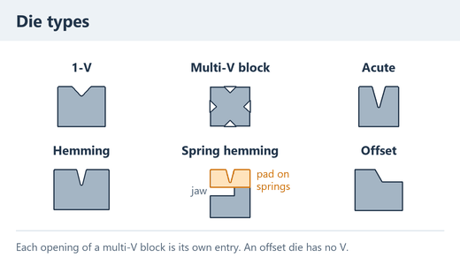
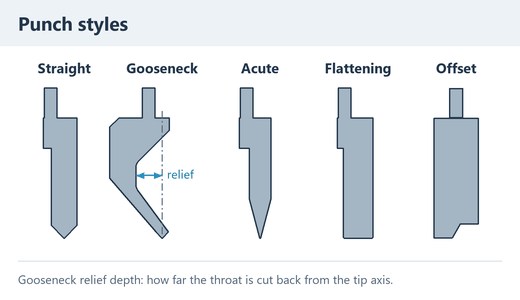
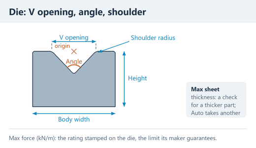
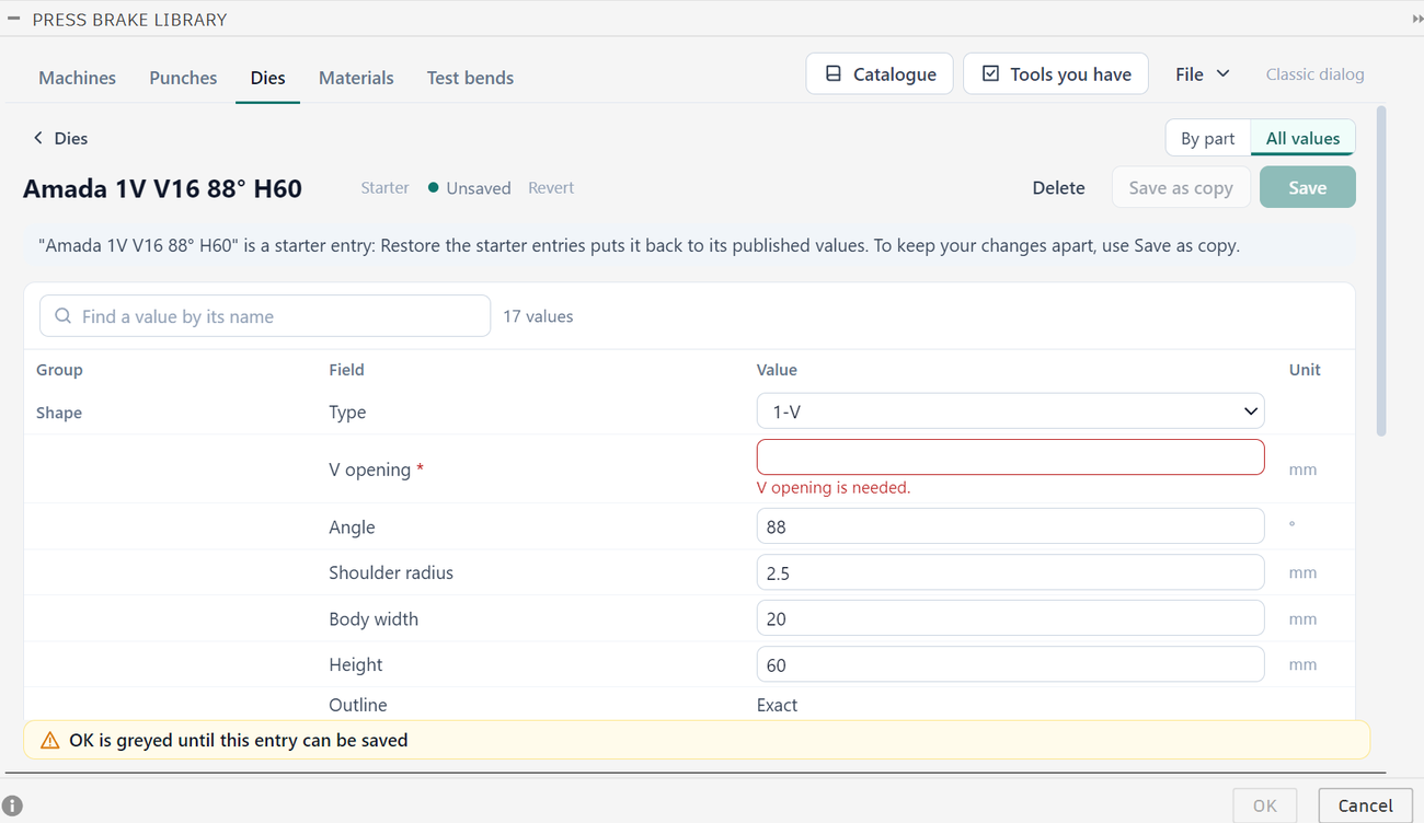
Click a row to open its entry, or + New for a new one; the name is the large box at the top. The values show in two arrangements, chosen at the top right and kept while the dialog is open:
- By part: a machine is drawn from the front and the side. Each part (frame and bed, ram, clamps, back gauge, controller, tool stations) opens its group of values when you click it, and each size the drawing marks (stroke, open height, X, throat...) takes you to its box. The box you are in, or hold the pointer on, lights its part and its size, and the line under the drawing gives its value and what it spans. A punch or die is drawn large from its outline with its sizes: a size and its box light each other, and clicking a size takes you to its box; a size drawn dashed is not given (the outline takes a typical value for it). A material has no picture: its groups stand in two columns.
- All values: one table of every value (group, name, value, unit); type in Find a value by its name to keep only those whose names hold the words.
- A box shows only its name, its value and its unit. What the value is for, and which checks read it, is in its tooltip. A red * marks a value the entry needs; a small amber dot, a value a check needs: its tooltip says which check is off without it, and the card Not checked lists them, each line a link to its box. Each group's title says how many of its values are given (5 of 7 given).
- A new entry shows only the values it needs; N more values shows the others of its group, and a click on a group's title opens all of it.
- Save saves the entry and stays on it; the message says what was saved and what that does to the lists. Save is greyed while the entry cannot be saved: its tooltip says why, and the box holding the problem turns red with the reason under it (a value missing, a name taken, a value that is no number). Revert, beside Unsaved, puts back the saved values.
- Values you type stay while the dialog is open. Leaving an entry you changed asks first: Save, Discard or Stay (only Discard or Stay while it cannot be saved).
- The form shows only the values of the die Type or punch Style chosen (an offset die has no V opening or shoulder radius); a hidden value keeps its value.
- Names are unique within a category. A renamed entry keeps its identity, so the setups stored on parts and its test bends follow it; the punches and dies made for a renamed machine (For machine) take its new name.
- To keep an entry as it is and save the values shown as another, click Save as copy: the copy takes the name you typed, or Name (copy) when you left the name, as its tooltip says. Start your own machine from a close one this way, or keep a reground punch apart from the starter entry it was (a starter tool's exact maker drawing comes along as the copy's own outline). A machine's copy does not take the tools made for that machine (For machine), so its lists and Auto do not use them; the tooltip of Save as copy says so before you save. To keep them, set their For machine to the copy, or rename the machine instead: its tools follow a new name.
- Delete asks first, naming what goes with the entry: a die, punch or material takes its test bends with it.
- A machine you add (a new one or a copy) becomes the one new parts start on.
| Category | Values you must give |
|---|---|
| Machines | Name, Tooling system, Max force (kN), Bending length. |
| Punches | Name, Tooling system, Style, Height. |
| Dies | Name, Tooling system, Type, V opening (not for an offset die). Each opening of a multi-V block is its own entry. |
| Materials | Name, Tensile strength Rm (MPa),
Air-bend radius (x V), K-factor (a number or
auto). |
The other values are optional; every entry also has notes and a Source URL. The fields whose meaning is not plain:
| Field | What it is |
|---|---|
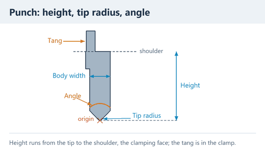
| Height of a punch | From its tip to its shoulder, the clamping face under the holder (not the tang): the upper beam is drawn there, and a formed flange taller than the Height is a warning. |
| Body width, Height of a die, V opening, Gooseneck relief depth | A punch's blade (a gooseneck's overall width, a flattening punch's face) or a die's block; a die from its top face down; the V's width at the shoulders; how far a gooseneck's throat is cut back from the tip axis. They shape the outline drawn from the values. |
| Max force (kN/m) | The load rating stamped on the tool, the limit its maker guarantees: enter your own tool's. |
| Max force, flattening (kN/m) | A hemming or spring hemming die's rating for pressing a hem flat, when the maker gives one apart: the flattening step is checked against it (against Max force (kN/m) when it is empty), every other step against Max force (kN/m). |
| Spring stroke (hemming jaw) | How high the jaw under a spring hemming die's V opens; 0 takes 13 mm (WILA DDU-001/1), as the outline line says. |
| Max sheet thickness | The thickest sheet the maker allows in the die or punch. Auto takes no such tool for a thicker part; one you choose yourself is yours to use, with a check on the bend sheet to remind you. Hemming tools are made for thin sheet: the DDU spring hemming dies 1, 1.5 and 2 mm, WILA's BIU-051 flattening punch and OZU-083 die 1.5 mm, Wilson's 51919 punch and 53594 die 16 ga. |
| For machine | See Tools made for one machine. |
| Grade | The sheet's short name (S235,
5052), used in the rule's name and to match a part's Fusion
material (Apply Bend Rule). |
| Standard, Yield strength (MPa) | An inch design prefers a material whose standard says ASTM. The yield strength is for your reference: no check uses it. |
| Springback at 90° (deg) | How far a 90° air bend opens when the ram lifts, in the usual die (an inside radius about the thickness): a first-trial value, which a test bend measured under load replaces (Springback). Empty: none is shown. |
+ New leaves empty what only your shop knows: a machine's Max
force, Bending length and X max (X min starts at 5 mm),
a punch's Height, a die's V opening, a material's
Tensile strength Rm; the entry cannot be saved, and OK stays
greyed once you typed in it, until the ones marked * are
given.
A new machine, punch or die starts at the tooling system of the machine
new parts start on (European (Promecam), or American in an inch design,
when that machine's is Other). An added material starts at
air-bend radius 0.16 × V, minimum inside radius 1 × t and
K-factor auto: change them for your sheet.
The Style or Type says what a tool is for: Auto tools + order bends with straight, gooseneck, acute and Other punches on 1-V, multi-V block and acute dies, and takes flattening punches and hemming or spring hemming dies only for hems and bends closed past 150° (Hems, Bends sharper than 150°), offset tools only for offset hits (Offset tools). It never picks a die of type Other, and replaces one chosen in the dialog: choose such a die by hand under Die.
Length fields use the document units; forces and strengths stay in kN, kN/m and MPa in an inch design. Convert American ratings: 1 US ton = 8.90 kN, 1 US ton per foot = 29.19 kN/m, 1 ksi = 6.89 MPa.
Machine values the checks use#
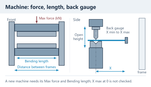
The checks use the machine values below. An optional value left at 0, in any category, is not given, and a check that needs it is skipped:
- Most are listed under Not checked, in the Bend Sheet dialog (with the value to fill in), on the bend sheet and on the machine's entry (each line a link to its value), and a plan from Auto tools + order is then only a candidate (Candidate found; geometry, capacity or bend-rule checks remain incomplete.).
- A few machine values that most makers do not publish are listed instead under Machine values not given (these checks are off), in the Bend Sheet dialog and on the bend sheet (on the machine's entry, under Not checked with the others), and leave Auto's plan as it is: Open height with the clamps, Max force on the table, Table width, the back gauge's X min, R lowest and R highest, R travel and Z travel, and Distance between frames and Throat depth when the part reaches into the frames.
- The station settings of Tool length: one piece or a sectioned set are the exception.
| Machine value | What the checks do with it |
|---|---|
| Controller | The machine's CNC. Choosing Delem, ESA, Cybelec, Estun or Langmuir sets the coordinate choices its manual settles and how a measured angle is typed on it; the others are named on the bend sheet (Your machine's coordinates). |
| Max force (kN), Bending length | A step that needs more force, or a part longer along its bend, is an error. |
| Max force on the table (kN/m) | The load a metre of the machine's table or tool clamps takes (TRUMPF TruBend 8000: 3000 on its standard clamps; LVD prints its table's): a step that needs more per metre is an error, as for a tool's rating. Left at 0, only the tools' ratings are checked. |
| Back gauge X min, Back gauge X max | The reach of the back gauge from the bend line (Back gauge); an added machine starts at X min 5 mm and X max not given. With X max at 0 the range is not checked. |
| Back gauge R travel, R lowest, R highest (from the die base), Z travel (along the bed) | How high and where along the bed the fingers reach. A step whose fingers stop the part on a face below R lowest or above R highest (its R above the die's top plus the die's Height; TRUMPF TruBend 1000: 50 to 250 above the lower tool clamp), two steps whose faces lie further apart in height than the R travel, or a stop face outside the Z travel (centred on the bed, where the step's station stands) is a warning; the fingers are placed within the Z travel. |
| Stroke | How far the ram lifts the punch after the bend; the section check, the 3D view and the 3D check lift it that far (with Open height with the clamps, no higher than the punch tip then stands above the die). Without it the withdrawal is not checked (ram withdrawal stroke), so no step's section check is complete. |
| Gauge retract during stroke | How far the back-gauge fingers move back once the punch pinches the sheet, on a step gauged on them; without it they stay at X (Assumed). |
| Upper clamp width, Upper clamp height (punch shoulder to beam), Upper beam thickness | Draw the clamp and beam of a machine without a clamp drawing (Tool and machine outlines). |
| Distance between frames, Throat depth | The side frames, solid behind their throat, in the 3D view and the 3D check. A part that reaches past them deeper than the throat at any point of the stroke (the flat sheet going in reaches furthest) is an ERROR: ... it meets the frame. The back gauge's fingers stay between them. |
| Open height | The table to the beam without tools, for your reference. |
| Open height with the clamps | The room the maker's upper and lower clamps leave for the punch and the die (TRUMPF: usable open height; an open height with the punch holders only, as AMADA prints it, is not it). With it and both tools' Height: punch and die that leave no room for the sheet with the ram up, or so short that the Stroke does not bring the punch down to the bend's depth, are an ERROR (... are too short for the machine, with how much taller they must be); and the ram lifts the punch after the bend only as far as that height leaves, so a part that cannot come out under taller tools is reported. Left at 0, the stroke alone counts. |
| Table width (lower beam) | The table under the die, this wide (or as wide as the die) and 200 mm deep, in the section check, the 3D view and the 3D check: a flange hanging down past the die meets it. The starter Durma, Bystronic, Harsle, SafanDarley and Langmuir carry their makers' widths; TRUMPF publishes none. |
| Ram approach speed, Ram bending speed, Ram return speed, Back gauge X speed, Back gauge R speed, Back gauge Z speed (mm/s) | The time a part takes (Time per part): the back gauge moves its X, R and Z at once, the slowest of them counting. The starter and catalogue machines carry their makers' figures where published; a machine missing a ram speed shows no time per part (the Bystronic Xpert Pro, the 2025 TruBend 8000 data and the TruBend 8320's return give none), and one missing the back gauge speed leaves the gauge's moves out (the starter AMADA HG-1003). The bending speed is the maker's highest: a CE machine bends at 10 mm/s at most. |
| Handling to re-gauge the part, Handling to turn or flip the part (s) | Your operators' times; left empty, 5 and 8 s (The Fabricator: turning the part, re-gauging it and starting the next bend take up to 5 to 8 s). |
| Tool change (s) | How long changing the tools on the bed for the next setup takes: the bend sheet gives 1 tool change a batch (about 10 min) for a part whose stations take more than one setup (Time per part). Your shop's own time; for a guide, a 3 m bed of 15 pieces takes about 570 s with bolted clamps and 116 s with quick-release levers (Rolleri), an automatic tool changer 3 to 4 minutes (AMADA, SafanDarley). |
| Y with the punch tip on the die top, Punch + die height at that Y, Y grows as the ram goes, Back gauge Z counted from, Opening counted from, Mute above the sheet, Angle on the controller | Your machine's own coordinates, so the bend sheet and the CSV give the angle, Y, Z and the opening as its controller takes them (Your machine's coordinates). |
Tooling systems#
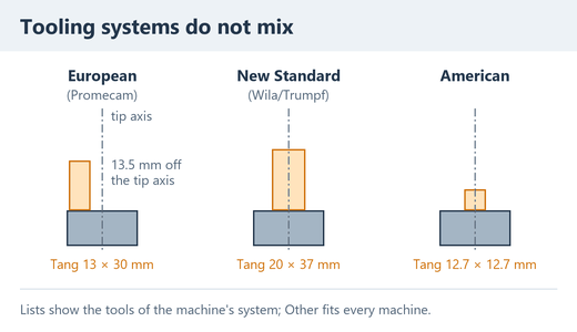
European (Promecam), American, New Standard (Wila/Trumpf), Bystronic and LVD tools do not fit each other's clamps, so Bend Sheet and Apply Bend Rule list the punches and dies of the machine's tooling system; a tool or a machine set to Other fits every machine.
- Choose the machine first: a die or punch that does not fit it is replaced by the suggested one (the 1-V die or multi-V block nearest 8 × t, a straight punch, else a gooseneck, before an acute one).
- When neither the part's setup nor your last use gives a machine, the first European (Promecam) machine is the default, in an inch design the first American one.
- An added machine, punch or die starts at the tooling system of the machine new parts start on (European (Promecam), American in an inch design, when that machine's is Other). With Other on any of them, the checks cannot confirm that the punch fits the clamp (verified tooling/clamping system under Not checked): set the system when you know it.
- A machine of system Other, Bystronic or LVD with no clamp drawing (its own or a starter machine's) and no clamp sizes is checked with a clamp that envelopes the common systems' clamps, larger than any one of them: a part may meet it where your clamp leaves room. Give such a machine its clamp sizes or outline.
Tools made for one machine#
A tool made for one machine (the Langmuir Titan set, say) names it under For machine, a list of your library's machines. On that machine it is suggested first (a die among those within 6 to 12 × t), marked Own set under Tools you have and switched on by Tick this machine's own set; the lists show the machine's name beside it. Only that machine's die and punch lists and its table under Tools you have show it, Auto tools + order uses it only there, and its tick counts only there; a part whose setup already has it keeps it. Choose (any machine) for a tool that fits all your machines. A renamed machine keeps its tools; a copy of it (Save as copy) does not. A tool that names a machine your library does not hold (an imported one, say) keeps that name, listed last.
Minimum inside radius by thickness#
This material field holds the minimum inside radius per thickness band,
in mm or as a multiple of t, as material standards give it. Write the
bands up to each thickness in mm: 1.5: 1.6 mm; 2.5: 2.5 mm; 3: 3
mm (EN 10025-2) or 3: 0.25 t; 6: 0.5 t; *: 1 t (EN
10149-2), * for any thicker sheet and - where
the standard gives no value. The bands win over Minimum inside radius
(x t).
Apply Bend Rule and Bend Sheet warn when the inside radius is below the minimum (cracking risk); with no minimum for the part's thickness, Bend Sheet lists that check under Not checked. Where a standard splits by rolling direction, the starter values are for bend lines across it; bends along it need a larger radius.
Tool and machine outlines#
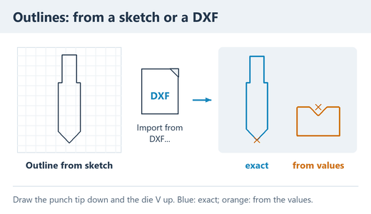
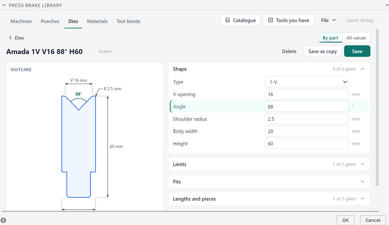
The checks and the 3D view need the outline of every punch and die and of the machine's upper beam and back-gauge finger. Each entry takes the best one there is:
- Its own outline (on a machine, its Upper beam outline and Finger outline), read from a DXF or a sketch, or typed in as points in the classic dialog (Entering an outline: points, a DXF or a sketch). It always wins. Tools added from the catalogue, and the UKB starter tools, have their maker's outline there.
- The maker's drawing of a starter tool (WILA CAD drawings; AMADA, Wilson Tool and Langmuir drawings measured to scale): with the UKB tools, 37 of the 38 starter punches and 73 of the 90 dies have one; most others are drawn from the maker's published dimensions. It stays while the entry keeps its catalogue shape (style or type, tooling system, height, body width, angle, tip or shoulder radius, relief, V, spring stroke); another name, rating, length or set keeps it.
- Drawn from its values: a straight, acute, gooseneck or flattening punch from its height, width, angle, tip radius and relief; a 1-V, acute, multi-V, hemming or spring hemming die from its V, angle, shoulder radius, width and height (and spring stroke). It follows the values; a value not given takes a typical one, named in the outline line. A tool of style or type Other needs its own outline (or its section is not checked); an offset tool needs none (Offset tools).
- The upper beam stands on the shoulder (clamping face) of whichever punch a step uses, on the tang axis: the machine's own outline, else a starter machine's clamp drawing (while its tooling system stays and it has no clamp sizes), else drawn from its clamp sizes, else the typical clamp of its tooling system. The starter clamps are the makers' drawings where published, else an equivalent clamp; none is exact. An older beam outline, drawn relative to the punch tip, is used as entered.
- The back-gauge finger: the machine's own outline, else a starter machine's, else a typical two-step finger of its tooling system.
Press Brake Library draws a punch's or die's outline beside its values, with its sizes (the tooltip of Outline says where it comes from); a machine's Upper beam outline and Finger outline say Given or Not given in its Clamps and tooling system and Back gauge groups:
| In the picture | What it means |
|---|---|
| Blue | Exact: its own outline, or a maker's CAD drawing. |
| Orange, tagged approximate | Drawn from the values, a typical shape, or an inexact maker's drawing. |
| A size drawn dashed | A value not given: the outline is drawn with a typical one, which the size shows. |
The classic dialog draws the outline with its origin (a red cross), a punch's Height as a dashed line at the shoulder, and a machine's beam on a grey 100 mm reference punch and its finger beside a strip of sheet.
The checks list every outline that is not exact under Assumed, in the Bend Sheet dialog and on the bend sheet, and Auto tools + order tries the tools with exact outlines first. To go back from an outline of its own, clear its field in the classic dialog: a starter tool that keeps its catalogue shape gets its maker's drawing back; any other tool, also one from the catalogue or a UKB starter tool, gets the outline drawn from its values.
Entering an outline: points, a DXF or a sketch#
On the page an outline comes from a DXF drawing or a sketch. In the
classic dialog an outline field also takes JSON points
[[x,z],...] in mm, also in an inch design: 3 to 256 points of
a closed outline that does not cross itself. Typed points keep their
place, so give them the library's origin:
| Outline | Origin (x = 0, z = 0) |
|---|---|
| Punch | Its lowest tip point. |
| Die | The centre of its V, at shoulder level. |
| Upper beam | The punch shoulder (the clamping face), on the tang axis. |
| Gauge finger | Its stop face, where the edge of the sheet rests, at die shoulder level; its body toward +x. |
Import DXF, under a punch's or die's outline and beside a machine's outline values, reads a closed outline from a 2D ASCII DXF drawing, such as a tool maker's CAD file:
- It reads lines, arcs, polylines and placed blocks, and skips centre lines and other dashed lines, text, dimensions and circles. Arcs become chords within 0.1 mm.
- The largest closed loop is the outline, so delete a frame or title block, or export only the tool; smaller loops and open lines are left out and counted.
- Gaps of up to 1 mm between the lines (some makers' drawings leave them) are closed with straight lines, and an outline over 256 points is simplified; both are reported.
- Inches, centimetres and metres are converted to mm, other units are refused, and a DXF that states none is read as millimetres: check the sizes drawn on the outline.
- Draw the punch tip down and the die V up, as in the press: the punch origin moves to its lowest tip point, the die origin to the centre of its widest top opening at shoulder height. Beam and gauge outlines keep the drawing's coordinates.
Pick in a sketch, beside Import DXF, reads the outline of a punch, a die, or the machine's upper beam or back-gauge finger from a sketch in the open design: Fusion's Outline from sketch pick shows under the page until the outline is read:
- Click inside the closed outline, or pick its curves one by one, all in one sketch. Regions picked together join into one outline (a tang drawn as its own region, say), construction lines are skipped, and until the curves close the message names the open ends.
- The sketch is read in millimetres as the Front, Right or Top view (whichever faces it) shows it, with the design's up axis up: draw the punch tip down and the die V up, anywhere in the sketch. For the upper beam the sketch origin is the punch shoulder on the tang axis, for the gauge finger X at shoulder level.
- A maker's STEP model becomes an outline by projecting its end face into a sketch.
- The outline updates at once: check it before you save the entry, and on a punch set Height so its size reaches the shoulder.
Tool length: one piece or a sectioned set#
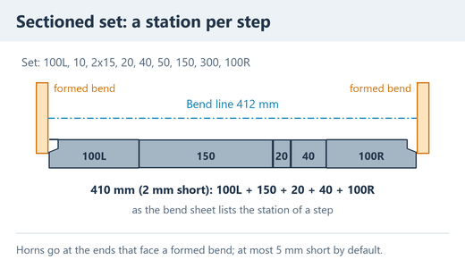
A punch or die is one piece of its Working length (along the bend),
or a sectioned set, its Pieces: the pieces the shop has, in mm or with
in, horns marked L and R, 2x15 for two pieces,
*x835 for as many 835 mm pieces as needed. AMADA's 800 mm set
reads 100L, 10, 2x15, 20, 40, 50, 150, 300, 100R.
With both, the set is used; with neither, the tool is taken as long as the bend line and listed under Assumed. The starter tools carry the sets their makers publish (AMADA, WILA, Wilson Tool, the Langmuir Titan kits).
For each step the add-in builds a station from the set, as press-brake controllers and offline programs do:
- It covers the bend line, short by at most the machine's Tool shorter than the bend line by at most; a short station is centred, half the shortfall at each end.
- It stops where the inside radius of a bend formed across its bend line starts, on its own side of the sheet (flanges formed up stop the punch, flanges formed down the die): a tool pushed into a formed radius bulges the corner.
- Between two formed bends (a box) it is as long as the room allows; otherwise it may run past the bend line and takes the fewest pieces, one solid piece when one covers it. Next to a single formed bend it moves to the free side.
- The pieces butt, or spread to reach the length up to the machine's Gap between tool pieces at most (x t).
- A horn goes at each end that faces a formed bend, then the long pieces
at the ends and the short ones inside. The Horn relief (setback
x tip band x height), in mm also in an inch design (
35 x 10 x
        35
for the AMADA AFH ear), lets the return of a formed wall pass; its setback must be shorter than the horn. The 3D view and the 3D check model it; a horn without one is checked as a plain piece.
| Machine setting | Starts at | What it does |
|---|---|---|
| Tool shorter than the bend line by at most | 5 mm | The Delem "tool length tolerance", the Cybelec "negative tolerance". 0: every station covers the whole bend line. |
| Tool end clear of a formed bend by at least | 0 | Room for placing the part by hand. 0: a tool may run up to the formed radius. |
| Gap between tool pieces at most (x t) | 0 | Up to 1 t on steel and 0.5 t on soft aluminium leave no visible mark (WILA); on an aluminium material the gaps stay at 0.5 t or less, whatever you enter. 0: the pieces butt. |
Max force, pieces and Max force on a horn (kN/m) are
checked on the steps whose station uses the set or a horn. The
*x pieces are the solid ones: a station made only of them
keeps the tool's own Max force (kN/m), and when a station of the
set is above Max force, pieces, the add-in builds one of solid pieces
where it can.
A one-piece tool longer than the machine's Bending length, or a
station that cannot be built (too short, or no room between the formed
bends), is an error of that step. The dialog, the bend sheet's tools table
and the CSV give each step's station, for example 295 mm (2.3 mm
short): 100L + 50 + 15 + 15 + 100R.
Starter library#
Every command uses the starter library until the library is first saved (a Save, Add, Save all or Restore in Press Brake Library, its OK with a change, or a test bend stored), which writes it to your library file with your change. Every starter entry quotes its published source in its notes (and in Source URL where there is a link); a value the source does not publish stays empty, never estimated. Your holders, clamps and back-gauge fingers still need your own data. See tool sources.
| Starter entries | What they are |
|---|---|
| Machines | From the makers' data sheets: Langmuir Titan 25T (American tooling), TRUMPF TruBend 7036 and 5130 and SafanDarley E-Brake 35-1250 (New Standard), Durma AD-R 30100 (European), Bystronic Xpert Pro 100/3100, Amada HG-1003 and Harsle WE67K-100T3200 (tooling system not stated by the maker: Other). |
| European (Promecam) tools | The AMADA NEW AFH catalogue (punches, 1-V dies V4–V80, 30° dies, a 4-V block, hemming dies) with its load ratings, and 12 UKB stock tools, each one piece of 415 or 835 mm, with outlines from UKB's CAD. |
| American tools | The Wilson Tool American Precision and Planed catalogues (punches, staged 1-V dies 1/4–2 in, 30° dies, hemming and flattening tools, 4-way blocks) and the Langmuir Titan 25T set, made for that machine. |
| New Standard tools | The WILA catalogue (punches, dies V4–V100, 30° dies, a hemming die) and the DDU spring hemming dies, with WILA's printed values and outline drawing. |
| Materials | S235JR, S275JR and S355J2C (EN 10025-2 bending radii), A36 (ASTM A6), DC01 and A1008 cold-rolled, DX51D+Z and A653 galvanized, S355MC and S700MC (EN 10149-2), Hardox 450, stainless 304, 316L and 430, aluminium 1050A, 3003, 5052, 5754, 5083, 6061-T6 and 6082-T6 (EN 485-2), copper Cu-ETP and brass CuZn37. Rm is the middle of the standard's range, or the published value; the air-bend radius share of V is the published one (The Fabricator, S. Benson; the Langmuir manual), else 0.16 × Rm / 413.7 MPa. |
Starter entries added in a later version appear in your library by themselves, without the I have this tool tick; one whose name an entry of yours has comes in as Name (2). A starter entry you delete stays deleted, and an update leaves the values of your starter entries as they are. A maker's value a later version gives a starter tool whose entry leaves it empty (a hemming die's Max sheet thickness, a rating) is filled in when a library saved by an earlier version is opened; a tool's length and sectioned set come only with Restore the starter entries.
A library saved by an earlier version keeps its entries; one without a tooling system gets Other, so a starter tool loses its maker's drawing until you restore it.
File > Restore the starter entries… lists first every starter entry you changed, renamed or deleted, by category (its tooltip names the values changed); Restore then puts them back to their published values. Your own entries and the I have this tool ticks stay. A dated copy of your library as it was is written beside it first, and the message names it.
Import, export and the library file#
The library is one file, press-brake-library.json, in the
add-in's data folder (About,
updates and your data); the screen Library file (opened by
File > Restore the starter entries…) gives its full
path at the bottom. Each save writes the file whole, so a save cut short
keeps the last good library.
| In the page | What it does |
|---|---|
| File > Export… | Asks where to write the whole library, with its ticks and test bends, for another computer or a backup. |
| File > Import… | Asks for a library file and
merges it into yours. An entry with the same id (a starter entry, or one
exported from this library) is replaced by the file's, its I have
this tool tick included; one whose name an entry of yours has comes
in as Name (imported). The file's test bends come too, each
replacing yours of the same material, thickness, die and punch, whatever
their dates. Your other entries stay. A dated copy of your library as it
was (press-brake-library-backup-2026-11-01-120304.json) is
written beside it first, and the message names it. An import
removes nothing, so importing that copy puts back the values and ticks
of the entries the import replaced but keeps the entries and test bends
it added; to go back fully, close the dialog and put the copy in place
of press-brake-library.json, under that name. A file with
a value the add-in cannot use is refused
whole, the message naming the entry: Dies, "Amada 1V V16 88°
H60" (entry 38): Max force (kN/m) must be a number. |
| Test bends, the bin of a row | Deletes that test bend, after a question in its row (each row names its material, thickness, die, punch, K-factor and date). Apply Bend Rule then uses the material's K-factor or the formula again; a rule applied before keeps its values until you apply it again. |
When the file cannot be read (after an edit by hand, say), Bend Sheet, Apply Bend Rule and Calibrate from Test Bend show only The press-brake library could not be read. and the reason; Press Brake Library adds Fix or move the file: and its path.
Fix the file, or move it out of its folder: every command then uses the starter library until you save, and File > Import… brings back the entries of a copy you exported, or of a backup copy written before a Restore or an import (the error of a file it cannot read names the entry to fix). The forming tools have a file of their own (Forming Tool Library).
Apply Bend Rule#
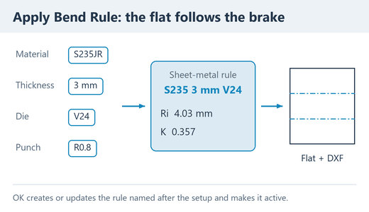
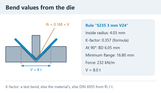
Apply Bend Rule gives a sheet-metal part the inside radius and K-factor of its material, die and punch, so that its flat pattern and DXF match the press brake. Run it while you design, or when a Bend Sheet check asks for it.
- Run Apply Bend Rule. Sheet-metal body holds the first sheet-metal body of the active component, else of the design.
- Pick the Machine first: the Die and Punch lists show the tools that fit it (Tooling systems, The tools you have).
- Pick the Material, Die and Punch (Thickness is the part's), read the box and click OK.
The dialog starts from the part's stored setup, else (here and in Bend Sheet) from the machine, material and punch you used last. A Fusion material that names a grade (Aluminum 5052 gives Aluminium 5052-H32) or a kind (stainless, aluminium, galvanized, copper, brass, steel) picks the material; Fusion's default Steel does not replace the material you used last.
The die is the part's own, else the machine's 1-V die or multi-V block nearest 8 × t, of your ticked dies when you ticked any: one within 6 to 12 × t when there is one (one made for the machine first), else the nearest of them all anyway (a CHECK then says how many times the thickness its V is); also in place of a stored offset die. The die list starts with the dies within 6 to 12 × t, nearest 8 × t first. Typing another Thickness keeps the die.
| Line | What it shows |
|---|---|
| Rule "S235 3 mm V24" | The rule OK writes. |
| Inside radius (air bend), K-factor | What the setup gives, the K-factor with its source: test bend and its date, material or formula. |
| At 90° | The bend allowance and bend deduction of a right-angle bend. |
| Minimum flange, Force, V = 8.0 t | The shortest outside flange that spans the die at 90°, the air-bending force per metre (formulas under Checks), the V in sheet thicknesses. |
| Now | The part's rule: name, thickness, Ri and K-factor. |
| The thickness changes ... | In orange: Thickness is not the part's. |
| CHECK lines | In orange: warnings, repeated after OK; OK still applies the rule. |
| The dialog says | What to do |
|---|---|
| V ... x the thickness; 6 to 12 x is usual. | Pick a die in that range. |
| Inside radius ... is below the material minimum ...: cracking risk. | A wider V, or a punch with a larger Tip radius. Shown only when the material has a minimum for that thickness (Minimum inside radius by thickness). |
| ... is above the die limit ... (or the punch limit) | A wider V needs less force; the limit is the tool's Max force (kN/m). Bend Sheet checks the machine's limit. |
| An offset die makes no air bend ... | OK stays off: pick a bending die. |
If Thickness is not the part's, OK first asks The sheet thickness of ... changes from ... to ... Continue? (No changes nothing). OK then writes a design sheet-metal rule, makes it the part's active rule, stores the setup on the part and keeps the machine, material and punch for the next part. Fusion recomputes the bends and the flat; Undo takes it back.
- The rule's name is the material's Grade (else its Name), the thickness and the die's V: S235 3 mm V24, or A36 0.125 in V0.63 in an inch design.
- A new rule is a copy of the part's current rule, so its other settings stay.
- A plan Bend Sheet stored on the part keeps its order, bumps and bend methods; with another machine, material, die or punch, each step takes the part's tools and gauge side again (What Bend Sheet keeps).
- An existing rule is reused only when its thickness, radius and K-factor match. Otherwise a numbered rule, such as S235 3 mm V24 (2), is created. Applying another calibration to one part does not change the rules or flat patterns of other parts.
- Bends that keep their own inside radius (a bend override, a body converted to sheet metal) are listed after OK: their flat follows the K-factor, not the press-brake radius. Edit them in Fusion to use the rule's bend radius.
Ri and K come from a test bend of this setup (Calibrate from Test Bend), else from these formulas; Fusion makes the flat pattern from them:
| Value | Formula |
|---|---|
| Inside radius Ri | V × the material's Air-bend radius (x V) (about 0.16 for mild steel, 0.21 for 304 stainless, 0.11 for 5052 aluminium), or the punch's Tip radius when larger. |
| K-factor | The material's K-factor when it is a number
(material); for auto, DIN 6935: K = (0.65 + 0.5
log10(Ri/t)) / 2, kept between 0.2 and 0.5, and 0.5 from Ri = 5 t
(formula). |
| Bend allowance BA | θ (Ri + K t), θ being the angle the flange turns, in radians. |
| Outside setback OSSB | (Ri + t) tan(θ/2), from where the bend begins to the outside virtual sharp: the corner where the outside faces of the two flanges meet when extended. |
| Bend deduction BD | 2 OSSB − BA. |
Calibrate from Test Bend#
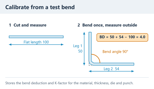
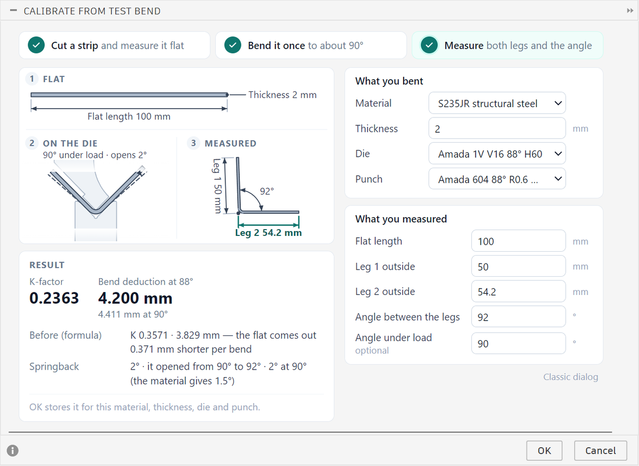
Calibrate from Test Bend works out the real bend deduction of a setup (material, thickness, die and punch) from one bent strip and stores it, with its K-factor, for Apply Bend Rule and Bend Sheet. It opens as a page: the three steps of a test bend along the top, the strip drawn in three pictures, and beside them the values in two groups, What you bent and What you measured. Point at a value, or reach it with Tab, and its size lights up in the pictures; point at a size and its value lights up. What each value is for and how to measure it is in its tooltip.
- Cut a strip and measure it flat. Pick its Material, type its nominal Thickness (as the part's rule has it, not a caliper reading) and its Flat length, end to end.
- Bend it once on the setup's die and punch, within about 1° of 90°: away from 90° the caliper reading is off, more so in thick sheet. Pick the Die and Punch.
- Measure each leg from its end to the outside virtual sharp (Apply Bend Rule), which a caliper over the leg reads at 90°, and the angle between the legs as a protractor reads it (90 for a right angle): type Leg 1 outside, Leg 2 outside and Angle between the legs. Read the result and click OK.
Point at a step and its values light up; click it and the first of them not typed yet takes the cursor. The pictures: Flat, the strip as cut, with its length and thickness; On the die, the strip bent on the die under the punch, each drawn from its own outline; Measured, the strip as it lies on the bench, each leg to the outside virtual sharp (the dot, where the two outside faces meet when extended) and the angle between the legs. A size whose value is not typed yet is dashed and says only its name.
To measure the springback as well, type the Angle under load (optional): the angle between the legs with the punch still down, the one the ram depth was set for with no springback correction (as the controller takes it), or one measured with the punch down. On the die then shows the strip at that angle and its legs opening when the ram lifts (drawn a little wider than they open), with both angles under its title. Bend Sheet then uses that springback for this setup instead of the material's (Springback); the same angle as the angle between the legs is a springback of 0, kept as measured. Left blank (or 0), a test bend keeps the springback the older one of the same setup measured.
The Die and Punch lists start with the tools of that machine, as Bend Sheet lists them (the dies for the thickness first), then the others of the library; once you ticked tools you have, they hold only those (The tools you have). A test bend counts only for the same material, die and punch, at a thickness within 0.005 mm.
| The result shows | What it is |
|---|---|
| K-factor | The one that gives the measured bend deduction with the die's inside radius. The radius is not measured, so the K-factor can differ from a book value; the bend deduction is as measured. |
| Bend deduction at ... | Both legs minus the flat length, at the bend (180° less the angle between the legs), and what that K-factor gives at 90°. |
| Before | The material's or the formula's K-factor and bend deduction, and how much shorter or longer the measured value makes the flat per bend. |
| Springback | How far the bend opened, and what that makes at 90° (a bend springs back in proportion to its angle); or which springback is used when it was not measured. |
| OK replaces the test bend of ... | The date and K-factor of the setup's older test bend, in the line at the bottom; Test bends in Press Brake Library lists them all. |
When a value cannot be right, the words go under its box, in red, and OK stays off until it is fixed:
| The page says | What to do |
|---|---|
| The two outside legs must add up to more than the flat length ... (under Leg 2) | Measure both legs to the outside of the bend, and the strip before bending. |
| The measurement gives K-factor ..., outside 0..1. ... (in the result) | Check the flat length, both legs and the angle. |
| Type the angle between the legs, above 0 and below 180 degrees ... | Type what the protractor reads between the legs: 90 for a right angle. |
| An offset die makes no air bend ... | Pick the die the strip was bent on. |
| The bend opens when the ram lifts: the angle under load must be no wider ... | Under load the legs stand closer: type the angle between them with the punch down, or leave it blank. |
| ... is not a value. | Type a number, in the design's
unit or with its own (2 mm, 0.08 in). |
In orange under a box, a value that makes a test bend but looks wrong: a leg shorter than the sheet is thick (measure it to the outside of the bend), or an angle under load of 180° or more, read as not measured. OK stays on.
OK saves the test bend in the press-brake library; no part changes until you run Apply Bend Rule on it again or accept the rule Bend Sheet offers (Write the shop files). A later test bend of the same setup replaces the older one (to delete one: Import, export and the library file).
Changing the physical tool or material values, such as the die's V opening, the material's Air-bend radius (x V), the punch's Tip radius or a tool's section, invalidates its affected test bends. The library reports the removed calibrations; repeat the test bend. Renaming an entry or changing its notes or ownership ticks keeps its calibration. New test bends also record the physical setup so stale measurements are not reused after a library import.
Bend Sheet#
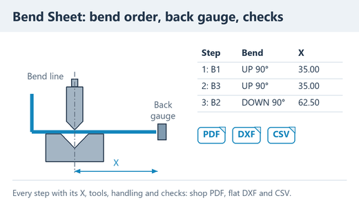
Bend Sheet plans how a sheet-metal part, with or without forms, is bent on your press brake. The plan gives the bend order, each step's die, punch and back gauge X, how the part is turned between steps, and the checks; OK writes it as a shop PDF, a layered flat DXF and a bend-program CSV.
- Parts: Selected part plans the part of the body under Sheet-metal body (one is selected when the dialog opens); All sheet-metal parts in the design plans every part: pick one under Part to see and change its plan. Auto tools + order and Check all steps in 3D work on the part shown. The next Bend Sheet opens on the choice you made.
- The lines under Part sum up the part (thickness, flat size, bends, rule with Ri and K-factor), the notes from reading it, Auto's last result and the punch and die of the steps, one line for the steps that share them (B1-B4: ..., with their stations), or say why the part cannot be read.
- Orange lines under it say what to look at first:
- ... is the starter library's first European machine, not one you chose ...: no machine was stored with the part or used before, so the plan is checked against a starter machine (the first American one in an inch design). Pick yours under Machine, or add it in Press Brake Library; the line goes once you pick one.
- No tool is marked as yours ... (or No die ..., No punch ...): the lists and Auto take every tool of the library that fits the machine, but those made for another machine (The tools you have).
- No die or punch of the ... tooling system is in the library ...: the lists are empty and nothing can be planned. Add the machine's tools (the line names the catalogue groups that hold them), or set its Tooling system to the one your tools fit. The dies and punches of the ... tooling system in the library are made for ...: they are another machine's own (Tools made for one machine); set their For machine to this machine or (any machine), or add its own.
- Auto's tools for B2 do not fit this machine ...: see Die and punch per step.
- The machine ... is not available now ...: see What Bend Sheet keeps.
- Choose Folder..., the OK button, is greyed until an output is ticked and a part is planned.
Fusion keeps one flat pattern per component, so Bend Sheet reads one part per component, the body its flat pattern is made from; another body is shown with that reason and the fix: right-click it in the browser and choose Create Components from Bodies. A part without a flat pattern gets one from the largest planar face of the body selected.
- A solid that is not sheet metal, such as a STEP import, is not read (... has no sheet-metal body): convert it first with Fusion's Convert to Sheet Metal.
- A part with no bends has no steps; its flat DXF still holds its outline.
- Forms made by this add-in are placed in the flat for the checks (see Forms near a bend); the forming-tool qualification that Manufacturing Export checks does not stop Bend Sheet.
The bend table#
The Bend order table lists the steps in the order they are made on the brake. Its columns: Step (3: B2, with ! when the step has an ERROR or a CHECK), Bend (UP or DOWN, the angle and a note), and X, Gauge and Handling (see Back gauge).
Bends are named B1, B2… from left to right in the flat seen from its top face, and keep their names in any order. UP folds the flange toward the top face, DOWN away from it: an UP bend is made with the top face up, toward the punch.
The notes, also on the PDF and in the CSV:
- pre (pre-bend on the PDF and in the CSV) and from 45°: Pre-bends;
- flattened from 150° (... to a 2.0 mm gap, ... to a teardrop): Hems;
- bump 2 of 7, on the second of B5's 7 hits made: Bump bending;
- offset with B4: Offset hits;
- bottomed, coined: Bottoming and coining.
Auto tools + order#
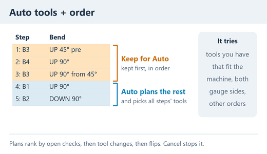
Auto tools + order plans the part shown: the bend order and each step's die, punch and gauge side.
It searches the punches and dies you have for the machine (see The tools you have, Tools made for one machine): the dialog's punch and die first, then straight punches and dies near 8 t, acute tools last unless a bend is over 95° (for the outlines it prefers, see Tool and machine outlines).
It tries both gauge sides and other orders, and prefers the plan with the fewest checks its tools leave open (a missing rating or outline, say), CHECKs and light contacts, then the fewest tool changes (one pair for the whole part when it is no worse), reliable gauging and fewer turn-overs. For an open-angle chain it also tries working from the middle out, so a flat edge can remain available for gauging. This is a preference, not a rule: the actual gauge contact, machine limits and collisions decide.
Among plans with equivalent checks, reusing one punch/die pair takes priority over fewer preliminary hits, easier gauging or fewer turn-overs. Auto also tries compatible pairs elsewhere in the machine's library, even if its first plan did not use them. A preliminary bend can be kept when it avoids a tool change. Locked tools stay locked, and a common pair is not accepted if it introduces a collision or a failed check.
Auto has one 40-second budget for searching and verifying candidates, including 3D checks. It can finish earlier when further trials are not useful. A geometry or plan calculation already in progress may finish after that budget. It keeps the best candidate found; reaching a time or sample limit is not proof that a part cannot be made. Unfinished checks remain marked as incomplete. Cancel stops it and keeps the plan you had.
Every step it tries gets the section check, and a part longer than the room between the machine's frames the frame check, so Auto gauges the side that keeps the deep part in front. When the flat can be refolded, a plan that clears is also folded in 3D within that budget, including a sampled route for taking it out. A step that meets a tool is searched again: with taller punches or in another order for the upper beam or clamp, with other tools for the punch or die. A plan is clear only with no ERROR, no CHECK but light contacts, and every step checked: a step the 3D check could not check, or an error the library's tools cannot avoid, leaves it a candidate, and the line at the top of the dialog says which.
Your order and Auto#
Auto tools + order keeps what you set by hand:
- your pre-bends, each before the step that finishes its bend (right before it only when nothing else fits); after a pre-bend Auto tries a bend beside it, then the finish;
- your offset hits, with offset tools (see Offset tools);
- your bumps, the hits of a bend one after the other, from either end, with one punch and die; only when no plan does them so (in a U, the last hit can meet the beam) does Auto make one earlier or use other tools for some (Bump bending);
- the steps you bottom or coin, whose tools must take that force.
If ordinary full bends leave a problem, Auto can try one or two extra pre-bends and several partial angles before finishing those bends later. It preserves the pre-bends and kept steps you set by hand. The result lists the pre-bends it added; their angles are turns from flat (a 30° turn leaves a 150° included angle). This is a bounded search, not every possible sequence or partial angle. You can still add, change or remove a pre-bend by hand and run Auto again.
For a hard feature (a bead, an offset with its pre-bends), let Auto plan only the rest:
- Set the order by hand up to the end of that feature.
- Tick Keep for Auto on its last step (Selected step).
- Click Auto tools + order: it keeps those steps first and plans the rest. A kept step keeps the die and punch you set for it (Die and punch for that step) and the side you turned it to (Turn front to back); Auto picks those you did not set.
After Auto, a step keeps the side Auto turned it to; the others take the side with the shorter X, also when you move them.
When Auto finds no plan#
When Auto finds no plan, a message says why. After every run, a line at the top of the dialog, and Tool search on the bend sheet, say how far the plan is checked, until you change it by hand:
| The dialog says | What to do |
|---|---|
| Auto tools + order found no plan: No die or punch of the ... tooling system is in the library ... | The machine has no tools to search: add them (the message names the catalogue groups that hold them), or set the machine's Tooling system to the one your tools fit. |
| No die and punch in the library can make every bend of this part on ... (No valid plan found ...) | Add the tools a step needs in Press Brake Library, or tick more of yours (Tools you have) when only the ticked ones were searched. |
| Auto tools + order found no plan for ... in its time. (Search limit reached ...) | Fix the steps left open (below), or plan the hard part with Keep for Auto (see Your order and Auto), then run Auto again. A search limit is not proof that special tooling is necessary. |
| No plan clears in 3D on ... (No plan clear in 3D was found ...) | Auto keeps the plan with the fewest steps that meet a tool in 3D, listed by its 3D check: give them taller or other tools, or another order. |
| Candidate found; geometry, capacity or bend-rule checks remain incomplete. | Read the CHECKs, Not checked items or incomplete section checks left under Checks. |
| The best plan found has an error no punch and die in the library avoid: ... | The error is the part's or the machine's (the frames, say): fix it from its ERROR (see When a check fails), on another machine if it says so. |
| ... the 3D check could not check step 3 (time limit) | The sections are clear; check that step by eye in the 3D view, or run Check all steps in 3D again. |
| No interference found in the sampled sections and axial wall checks. (... or the 3D check. after the 3D check) | Nothing: every check ran and passed, light contacts aside. |
| No interference found in the sampled sections and axial wall checks; the flat's bend rule differs from the die's. | Every check passed, light contacts aside, but the flat's K-factor or inside radius: the Bend rule line under Checks says what OK does with it (Checks). |
| Search cancelled; previous plan retained. | Nothing: you clicked Cancel. |
The first two messages also say how far Auto got (Made 4 of the 6 steps in one order; then B5: ..., with the tallest punch tried when a wall meets the beam). The order becomes the one that went furthest, with those steps' tools and gauge sides; when Auto made none, nothing changes.
The steps after them, from the first one marked !, are yours: fix each from its ERROR (see When a check fails) with Add a pre-bend, Move to step, Turn front to back or other tools (click its row, then its Die or Punch).
Notes then name the steps kept for Auto, the hems it pre-bent, your pre-bends it kept and the tools searched.
Bend order#
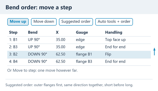
The bend order is where you change the plan by hand. Click a row to work on its step: the Selected step controls, the die and punch boxes and the 3D view follow it.
- Move up and Move down move it one place, but never a pre-bend after the step that finishes it.
- Suggested order puts back the starting order: outer flanges first (a bend with a free flange on one side), bends of one direction grouped to save flips, short before long, a hem pre-bent right before it is flattened, the hits of a bump bent bend one after the other. It takes out your pre-bends and splits your offset hits; each step's own tools, Turn front to back, bend method and bumps stay.
The Selected step controls act on the step selected; most are greyed without one:
| Control | What it does | Greyed on |
|---|---|---|
| Add a pre-bend / Remove the pre-bend | The bend in two hits, or in one again (Pre-bends). | an offset hit |
| Pre-bend angle | The angle of its pre-bend, or of the next one added. | – |
| Turn front to back | The other side of the bend to the back (Back gauge). | – |
| Bend method | Air bending, Bottoming or Coining (Bottoming and coining). | a hem's flattening, an offset hit |
| Make an offset hit / Split the offset hit | This bend and the one beside it that turns back in one stroke, or two bends again (Offset hits). | a pre-bend and its finish |
| Bumps | A large radius in this many hits, 0 for one (Bump bending). | a hem, a pre-bend, an offset hit |
| Move to step | The step to the place you pick. | – |
| Keep for Auto | Auto keeps the steps up to this one, in this order, with the tools and gauge sides you set for them (Your order and Auto). | – |
Die and punch per step#
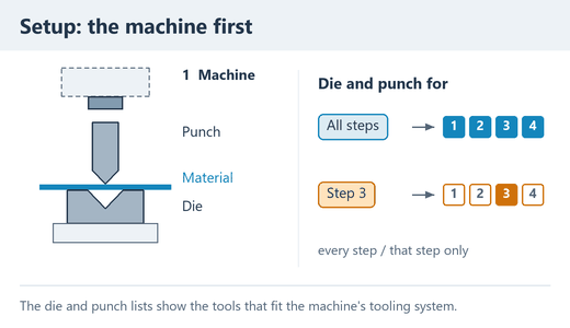
Die and punch for, under Press brake, chooses whose tools the Die and Punch boxes show and change:
- All steps: the part's; a change goes to every step.
- A step, also chosen by a click on its row: that step's; a change goes to it only. Choose All steps again before you change the part's tools.
Machine and Material are the part's; the next part starts on the ones you pick. Auto gives the part the die and punch most steps use, and their own only to the steps that need others.
- Changing Material keeps each step's own die and punch (with the new material) and gauge side.
- Changing Machine keeps them while they fit the new machine's tooling system. A step whose tools do not fit takes the part's, and an orange line names it (Auto's tools for B2 do not fit this machine ...): run Auto again. The gauge sides stay.
- Changing the die or punch with All steps gives every step the part's tools and the side it gauges by itself again, undoing each Turn front to back and Auto's sides.
The order, pre-bends, offset hits, bumps and bend methods stay.
Back gauge#
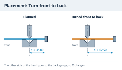
For every step Bend Sheet works out the back gauge X and the side that goes against the gauge, with the part as it is at that step.
X runs from the bend line to the farthest point of a side: the free edge of a flat side, or the outside of a formed flange (at 90°: the flat distance to its bend line plus half its bend deduction). The side whose X fits the machine's Back gauge X min to Back gauge X max goes to the gauge, the smaller X when both fit; when neither fits, the step has an ERROR.
Gauge names what rests against the gauge: the edge, a formed flange (flange B2), or in the die for a step that finishes a pre-bent bend, with no back gauge (X shows -).
The back gauge's fingers, for a controller with R and Z axes (and for setting them by hand):
- R: the height above the die's top of the face they stop the part on. The sheet's edge on the die is 0; a formed flange standing up is stopped above its outside radius ((Ri + t) at 90°: 5 mm for a 2.5 mm sheet with Ri 2.5); one hanging down, below the die's top (a negative R).
- Z: where the fingers go along the bend, from its middle: on the stretches of that face the part has there (a notch in the edge is left out), a finger's width (30 mm) in from their ends; one finger in the middle when they are shorter than three fingers. The back gauge runs between the machine's frames: on a part longer than the room between them, the fingers stand a finger's width in from the frames.
The 3D view draws the fingers at those Z places and the 3D check takes them as solids; the step's line under the view and the bend sheet's TOOLS BY STEP give R 0.0, Z -85.0 / +85.0.
Turn front to back puts the other side of the step's bend to the back: the part is gauged on its other edge or flange or, finishing a pre-bend, lies the other way round in the die. It changes that step only (a hit of a bump series: the whole series, its hits made from the other end); click it again to turn it back.
Handling: on step 1 Top face up or Bottom face up, then what changes from the step before: Same placement, Flip over, Turn end for end, Rotate 90° CCW (any angle, CW or CCW) or two of them (Flip over, rotate 90° CW). The bend order shortens Flip over to Flip (Flip + before a turn) and Turn end for end to End for end.
Your machine's coordinates#
What the operator types into a controller depends on where each of its axes counts from. The bend sheet and the CSV give:
| Value | Where it counts from | Typed as it is |
|---|---|---|
| Bend order, punch and die, material, thickness | - | Yes. |
| Angle | Between the flanges on the controllers whose manuals say (Delem, ESA, Cybelec, Estun E300: 90 a right angle, 135 a bend that turns 45°, 30 a hem's pre-bend); a hem or a closing pressed by a flat punch is set by its ram stop, no angle (a Delem's hem method with its opening), but on an ESA, which takes 0.0; the bend table gives how far the flange turns | The CNC ANGLE in TOOLS
BY STEP and the CSV's Angle on the controller, as your
machine's Angle on the controller says. A CNC programmed by the
angle works out its Y itself. |
| X | The centre line of the die's V to the back gauge's stop face, the zero back gauges are set to | Yes (a controller that takes the flange instead: the FLANGES column). |
| R | The die's top, as controllers with an R axis count it from the die's height | Yes. |
| Angle correction | - | Yes (Measured angle). |
| Y (depth) | Each machine's own Y scale | With your machine's Y reference (below); else the depth below the die's top. |
| Z | Each machine's own Z zero | With your machine's Z zero (below); else from the middle of the bend. |
| Opening | The die's top, the sheet's top or the mute point, by controller | With your machine's choice (below); else from the die's top. |
Set these once for the machine in Press Brake Library > Machines:
- Controller first: choosing it sets what its operation manual
settles, and you can change any of them after (a machine builder can
set an axis the other way):
Controller Sets A measured angle is typed as Delem DA-53T, 58T, 66T, 69T Y grows down, opening from the mute point, angle between the flanges correction -2.0° (measured 92°): programmed less measured Delem DA-41 Y grows down (a higher value means a lower beam position); its opening is a time the same ESA S630, S640, S650 Y grows up (its top dead centre, mute, pinch point and bottom in decreasing order), angle between the flanges the same Cybelec CybTouch, ModEva angle between the flanges measured 92°: type the measured angle (the control works out its Y) Estun E300 angle between the flanges the correction, as Delem Estun E21, E200P a Y only: no angle is typed (CNC ANGLE -), so set the Y reference below corrected in the Y: the Y already holds it Langmuir BendControl Y grows up (0 at the top, negative down), opening from its safety jog plane (the mute point), inside angle compensation 2.0° UNDERBENT (or OVERBENT) TRUMPF, AMADA, Bystronic, SafanDarley, Durma, LVD no public manual: named on the bend sheet only the correction - Y with the punch tip on the die top: with a punch and die in the machine, jog the ram down slowly until the punch tip just touches the die's top (a feeler between them), and read Y on the controller. Punch + die height at that Y: the punch's Height plus the die's Height, as the library has them. Another punch and die then move Y by the difference in their heights. (0 counts as not set: a machine whose Y is 0 there takes 0.01. A Y counted down from the top of the stroke, as on the Langmuir Titan, is below zero.)
- Y grows as the ram goes: Down when a larger Y is a lower ram (Delem), Up when it is a higher one (ESA, Langmuir).
- Back gauge Z counted from: the left end of the bed or its middle, as the controller's Z zero is. The step's bend stands where Tool setup on the bed puts its station, with the other parts set up with it.
- Opening counted from: the die's top, the sheet's top, or the mute point, where the ram changes from fast closing to pressing speed (Delem: a positive value is above Mute), with Mute above the sheet.
- Angle on the controller: Between the flanges (the default: every controller whose manual says), or Bend (turned) for one that takes how far the flange turns. Try it once on yours: type 135 and see whether its screen draws a shallow bend.
The bend table then shows Y instead of Depth, TOOLS BY STEP
says what Z and the opening count from, and the CSV has
Y, R, Z1, Z2,
Z from, Opening, Opening from and
Opening tilted, one row per step, as a controller's bend
table takes them. A brake
programmed by the angle needs no Y: the controller works it out. Bend
Sheet writes no program file for a controller: the operator types the
values, or loads the PDF beside the machine.
Depth and opening#
For a brake set by the ram position instead of the angle (an NC such as Estun E21 takes a Y position for each step), and for the controllers' own settings:
- Depth (bend order, bend table, CSV): how far the punch tip goes below the die's top at the bottom of the stroke, past the bend's angle by its springback (Springback) and any measured correction. From the punch touching the flat sheet, that is the depth plus the thickness. Bottomed and coined steps have one too; a hem's or a closing's flattening has its ram stop instead.
- Opening (TOOLS BY STEP, CSV): the gap between the punch tip and
the die's top the ram opens to after the step for the part to slide
straight out to the front. When the operator tilting it out takes less
(its front lifted or lowered on the way, as the removal check turns
it), that opening too: 36.15 (29.47 tilted), the CSV's
Opening tilted. In a spring hemming die's V both count from its top pressed shut, as the Y does: the springs lift the part with the punch their stroke before the punch leaves it. A small opening saves time (Delem). A Delem takes its Opening from its mute point, where the ram changes from fast closing to pressing speed: there, enter this less the mute's height above the die.
The depth comes from the bend's geometry (the section check's model), the sheet bearing on the die's shoulders as round as the die's Shoulder radius (sharp edges when it is not given): a round shoulder carries the sheet further out as the bend starts, so the punch goes a little deeper for the same angle. Set the first part, measure it and enter the angle it came out at (Measured angle).
Measured angle#
Measured angle, under Selected step, keeps the angle a part came out at after that step, as a protractor reads it: the angle between its legs, 90 for a right angle. A part bent to 90° that came out at 92° opened 2° too far, and the step is pressed 2° further (ADH: a 90° target releasing at 92° means starting about 2° farther closed).
- Its springback, the 3D view, the checks and its depth take it; the bend table, the PDF and the CSV give the correction as the controller takes it, to type into its angle correction: the angle programmed less the one measured, between the flanges (Delem, ESA, Estun: correction -2.0° (measured 92°), a negative correction closes the angle). A machine whose Angle on the controller is Bend (turned) gets it the other way round. The machine's Controller sets how it is written: a Cybelec takes the measured angle itself, a Langmuir its size with OVERBENT or UNDERBENT, an Estun E21 or E200P the Y alone (Your machine's coordinates).
- A bend closed past 150° by a flat punch takes it in its ram stop.
- It is kept with the part (OK saves it) for that step, its physical setup and calibration. A changed calibration or setup makes the old correction inactive and adds a warning to Checks and exports. Bend a new sample and enter its measured angle again. Older saved corrections whose original setup was not recorded also require a new measurement. Clear measurement removes the saved record, including an inactive one; setting an active measurement to 0 also clears it. Hems and offset hits have none.
Tool setup on the bed#
A part that takes two or more punch and die sets can be made without a tool change with the sets side by side across the bed, stage bending (The Fabricator: punch and die sets of a common shut height set up across the bed). Bend Sheet lays them out:
- one station for each punch and die as a step assembles them: a box's last bends between its walls, with a shorter punch or one with horns, take a station of their own;
- in the order the steps first use them, spaced so the part at one station does not reach the next (its reach along the bend, short of the walls already formed at its ends), centred on the bed;
- the sets on the bed together share a shut height, the punch's Height plus the die's: the ram closes them all at once, so a taller set's punch would plunge into its die while a shorter one bends. A set of another height, or the stations past the Bending length, take a setup of their own, each centred on the bed, a tool change between them. The frames are no limit here: tools and parts pass them within their throat (the frame check, in Machine values the checks use).
The parts open in Bend Sheet on one machine are set up together, as a shop sets up a batch to bend it without a tool change: those whose sets share a shut height, as many as the bed has room for side by side, take one setup, a station two of them use set up once. A part that would then reach into the frames deeper than their throat, or whose own stations take more than one setup, keeps its own. Each part's stations, its Z and its frame check follow the setup it is in.
The bend sheet's TOOL SETUP ON THE BED lists each station's punch, die, shut height, length, place on the bed from its left end and steps, with the SETUP of each when there are more, and the PARTS each serves when parts share it (TOOL SETUP ON THE BED, SHARED BY 2 PARTS); the step's line in the 3D view and the CSV give bed station 2 (480.0 - 520.0) mm. A part with one set alone on the bed has no such table. Staging pays for parts up to about half the brake's length (The Fabricator).
Time per part#
About how long a part takes on the brake, as cost models build it (each bend's machine time and handling, and loading the blank):
- the ram: down from the step's opening to the sheet at the machine's approach speed, bending to its depth (a flattening to its stop) at its bending speed, back up at its return speed;
- the operator: turning or flipping the part between steps (8 s), or moving it to the next X (5 s); the blank loaded as a turn, the part taken off as a re-gauge (The Fabricator: up to 5 to 8 s);
- the back gauge's move where it outlasts that handling.
The part block of the bend sheet gives about 40 s a part, the step's line in the 3D view the step's time and the part's, the CSV each step's. Set your machine's speeds and your handling times in the library (Machine values the checks use); without the ram speeds no time is given. A part whose stations take more than one setup needs tool changes: 1 tool change a batch (about 10 min) with the machine's Tool change time. They are not in the part's time: a batch is bent setup by setup, so they come once a batch.
Checks#
The Checks box lists what the plan cannot make and the risks to look at, step by step and for the whole part:
- ERROR (red): cannot be made; CHECK (orange): a risk. The ERRORs come first. Neither stops OK; the bend sheet prints them and the message after OK counts them.
- Auto tools + order often clears the errors below: click Auto.: first, above the ERRORs of a part with no plan of its own yet, until Auto has run on it: the suggested order does not look for collisions, Auto does (a U channel's second step meeting the punch, say). Bend Sheet does not run it by itself.
- Bend rule: the flat was made with ...: the flat's inside radius or K-factor are not those the die and punch give. This one line says how far out the flat is per 90° bend and what OK does with Apply the die's bend rule to the flat first under Outputs, and names the bends that keep their own radius. The bend table marks no step for it.
- No problems found.: no check failed; Checks incomplete.: none failed, but some could not run. The lines under them say which.
- Not checked: the checks that could not run, mostly for a value missing in the library, each with the value to fill (ram withdrawal stroke (the machine's Stroke, in Press Brake Library)).
- Machine values not given (these checks are off): the values of the machine its checks would use that its entry leaves empty, each with what it checks: Open height with the clamps, Max force on the table, Table width, Back gauge X min, R lowest and R highest, R travel (two steps on the fingers), Z travel, and Distance between frames and Throat depth when the part reaches into the outer tenth of the bed. Most machines leave some of them out, so they do not keep Auto's plan a candidate the way Not checked does.
- Assumed: the values taken in place of missing ones.
Every step is checked for its flanges, force, the machine's bed and back gauge, its tools' length (see Tool length: one piece or a sectioned set) and walls, and by the section check (see How the section check works). The whole part is checked for its tools, holes, radius, rule and forms (see Forms near a bend). Each line, and what to do about it, is in When a check fails.
| Check | Limit |
|---|---|
| Minimum flange | 0.7 × V, the shortest outside flange that still spans the die at 90°. |
| V-die shoulder support | For air bending, the finite flange section must reach both shoulder bearing points throughout loading, including overbend for springback. The check samples at most every 0.5°, using V and the shoulder radius. A CHECK identifies the front or back-gauge side and the approximate angle where support is lost. Holes, formed oblique walls or contact outside this motion model leave support unconfirmed. This is a section check, not a full-width load or stability analysis. A clear collision result does not cancel it. Auto considers the CHECK; export remains available for your review. |
| Force | F = 1.42 × Rm × t² / V kN per metre of bend (Rm in MPa, t and V in mm), against the die's and punch's ratings per metre and, over the bend's length, the machine's. |
| Holes | Holes and cut-outs at least 2.5 t + Ri from a bend line. |
| Walls | No formed flange, and no wall at the ends of the bend line, taller than the punch; no flange hanging down closer than V to the bend line (a short Z). CHECKs, dropped when the section check clears the step. |
When a check fails#
This table says what to do about each line under Checks. Special bends and forms have their own messages: see Pre-bends, Hems, Bottoming and coining, Bump bending, Offset hits and Forms near a bend.
| The dialog says | What to do |
|---|---|
| ERROR: flange, force, machine | |
| flange ... is shorter than the minimum ... | A die with a smaller V, or a longer flange. Between two bumps, the error says what to change: fewer bumps, a narrower die, or Bumps 0 for a bend one hit makes. |
| ... is above the die limit ... (or the punch, sectioned, horn or machine limit) | A wider V needs less force; else a tool rated higher or a stronger machine. |
| X ... is outside the back gauge range ... on both sides. | Another order (a flange formed earlier changes X), or check Back gauge X min and X max. A side set with Turn front to back stays even out of range (the line still says on both sides): click it again. |
| the part is ... long along the bend, the bed is ... | A machine with a longer Bending length. |
| the part reaches ... past the machine's frame ... deeper than its throat ...: it meets the frame. | A part shorter than the room between the frames: nearer the middle of the bed. Else Turn front to back when its other side is shallower, or a machine with a deeper throat or more room between its frames. |
| ERROR: tools | |
| Punch ...: or Die ...: with its length (short of ..., does not fit between the bends formed at its ends, its pieces make no station) | A longer or shorter tool, a sectioned set with the pieces it needs, or this bend before the walls at its ends (Tool length: one piece or a sectioned set). |
| ... does not match the machine tooling system. | A tool of the machine's tooling system. |
| ... sharper than the die angle ... (or punch) | Acute tools for that step. |
| ... it springs back about ...: to end at ... it must close to ... under the punch, but the die (...) stops it at ... | A die and punch sharper than the angle it says, or bottom the bend (Springback). |
| ... with the ram fully open (stroke ...) the part still stands round the punch ... (or cannot be lifted off the die ...) | Slide it off along the tool, or bend in another order or on a machine with a longer stroke (Taking the part out). |
| ... closing to ... is sharper than acute tools bend. | A pre-bend to 150° before it (Add a pre-bend), and a flattening punch for the step that closes it (Bends sharper than 150°). |
| Formed bend allowance zones overlap. | Move the two bends apart in the model. |
| ERROR: contacts | |
| Section intersects punch ..., ... meets the beam ..., ... is in the way of the die before the bend starts, ... 3D check: ... | A taller or gooseneck punch, another die or order, Turn front to back or a pre-bend: Auto tries these. |
| CHECK | |
| a formed flange stands ... high, the punch is ..., the wall formed at ... stands ... high | Left while the section check cannot clear the step: a taller or gooseneck punch or another order, then Check all steps in 3D. |
| ... is below the material minimum ... | A die with a wider V, or a punch with a larger tip radius. |
| ... takes sheet up to ...; this part is ... | A reminder: the die or punch you chose is made for thinner sheet (its Max sheet thickness). Auto takes no such tool; for a hem, use hemming tools made for that sheet. |
| a hole or cut-out is ... from the bend line ... | Move it in the model, or expect it to distort. |
| Bend rule: the flat was made with ... (on the bend sheet, when it is unticked: The flat uses K-factor ..., ... flat bend radius ... differs from the selected setup radius ...) | Leave Apply the die's bend rule to the flat first ticked under Outputs (see Write the shop files), or run Apply Bend Rule. No rule changes a bend with its own radius (a bend override, a converted body, a large radius; the line names it): edit it in Fusion, use a die whose radius matches, or bump bend it. |
| ... the inside radius could not be read from the flat pattern ... | That bend uses the rule radius: check it in Fusion. |
| ... a hem, made in two hits ... | Shown on every hem: how it is made (Hems). |
| the folded-back flange is ... long, the punch face ... | Flatten it in two places, or use a punch with a wider Body width. |
Most Not checked and Assumed lines name a value missing in Press Brake Library; in the dialog, a Not checked line says in brackets which one (see Machine values the checks use):
| The dialog says | What to do |
|---|---|
| die force rating, punch force rating | The tool's Max force (kN/m). |
| machine force rating, back-gauge X range, part longer than the bed, ram withdrawal stroke; Assumed: the back gauge stays at X during the bend | The machine's Max force (kN), Back gauge X max, Bending length, Stroke, Gauge retract during stroke. |
| bending force, flange shorter than the die minimum, formed flange taller than the punch | The material's Tensile strength Rm (MPa), the die's V opening, the punch's Height. |
| radius below the material minimum | See Minimum inside radius by thickness. |
| verified tooling/clamping system | A Tooling system left at Other: set it. |
| ... section geometry; Assumed: punch: ... (or die, beam, gauge) | Give it an outline, or an exact one (Entering an outline: points, a DXF or a sketch). |
| Assumed: ... length = the bend length | The tool's Working length along bend or Sectioned set (pieces). |
| air-bend motion | A V die, or a hem made in two hits (Hems). |
| large-radius bend | Bumps or a radius punch (Bump bending). |
| formed oblique walls ..., axial clearance ..., forms outside this section ..., section interrupted by holes ..., motion sampling resolution ... | Run Check all steps in 3D. |
| Machine values not given (these checks are off): ... | The machine's values it names, under Machines; until then their checks are off (the bend sheet lists the values too). |
Forms near a bend#
Bend Sheet checks the forms made by this add-in against every bend and takes them through each step's section check.
| The form | What Bend Sheet does |
|---|---|
| Reaches into a bend zone | ERROR: the bend crushes it or pulls it out of shape. |
| Closer to where the bend starts than 3 t + R (Mate); 15.88 mm for a louver made in a press-brake louver die (Protocase) | CHECK. |
| On a flange | Moves with its panel of the flat (a form beside a tab stays with the sheet it is joined to); one that rests on the die shoulders, hangs into the V or meets the punch or the back gauge is named: Step 2 (B2): The louver 8c4508 is in the way of the die before the bend starts. |
| On a wall formed across the bend (a box's end wall) | Not in the step's section: Not checked says so; the 3D check covers it. |
| Cannot be placed in the flat (on a rolled face, or over two flanges) | Listed: check its distance to the bends by hand. |
| A gusset across a bend | Listed with the tooling its bend needs: a punch with the rib notch and a die with a beading bar, or pressing it after bending. |
Pre-bends#
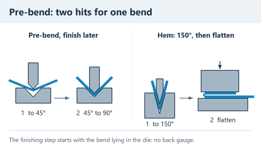
A pre-bend makes a bend in two hits: part way while the part is open, finished after the bends next to it. Use it when the tools would meet the bend at its full angle (a short offset, a bead between two walls).
- Select its row and click Add a pre-bend (Selected step): a pre-bend to the Pre-bend angle, 45° unless you type another, goes before it, and the finishing step is selected.
- Move that step down past the bends that need the room.
The finishing step starts with the bend lying in the die (in the die, no back gauge) and bends it on from the pre-bend angle. Each of the two steps has its own die and punch (Die and punch for) and placement; both rows take Pre-bend angle and Remove the pre-bend.
Hems#
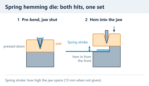
A bend of more than 170° is a hem, made in two hits. First a pre-bend to 150° with an acute punch and die (a hemming die's V as well), then the hem pressed flat by a flattening punch, the rest of the part lying on the die.
The suggested order and Auto add the pre-bend; Auto picks acute tools for it and a flattening punch on a hemming die for the flattening (on a V die only with a warning). The force is the hemming force (Benson's table, scaled by the tensile strength). A later bend gauges on the outside of the hem's fold.
- An open hem, whose flat leaves a gap inside it (Ri more than a tenth of the sheet), is pressed with the ram stopped 2 (Ri + t) above the die, or on a spacer as thick as the gap.
- A teardrop, past 180°, is pressed on its loop, with the same ram stop.
A spring hemming die (WILA DDU, Mate) makes both hits with one punch and die, with no tool change: the pre-bend in the V on its spring pad, which the punch first presses down onto the body (the jaw shut) and the springs lift again, then the hem pushed into the jaw under the pad, from the front, and pressed by the punch through the pad.
Auto pairs such a die with the punch that fits its V. The 3D view shows the pad going down and back up; the check says when the pre-bent hem stands higher than the jaw opens or the part would go in from the back.
Only a hem's flattening goes into the jaw. Any other step on a spring hemming die, the hem's pre-bend or a bend you put on it yourself, is an air bend in the V on its pad: the punch first presses the pad down onto the body (the jaw shut), the force is checked against its Max force (kN/m), its radius and K-factor come from its V, and the section check and the 3D view show the pad going down and the springs lifting it after the bend. Auto takes such a die for hems only; you can choose it for any step under Die and punch for.
Auto takes only the hemming tools whose Max sheet thickness takes the sheet: on a WILA machine 1 mm goes in the DDU V6 and 1.5 to 2 mm in the V12, both hits on that one die; a thicker hem needs a flattening punch and die made for it, and without one Auto finds no plan and names the limit (... takes sheet up to 1.5 mm; this part is 2.5 mm).
Bends sharper than 150°#
Acute punches and dies air bend down to 30° inside, a bend of 150°. A bend between 150° and 170° (20° inside, say) is made as a hem is, in two hits: a pre-bend to 150° with an acute punch and die, then the bend closed by a flattening punch on a hemming or flat die (or in a spring hemming die's jaw), the ram stopped where the flange stands at its angle. That is what flattening dies are made for: to close a previously formed acute angle to a given degree of opening (Rite-Way), or to complete a hem.
The suggested order and Auto add the pre-bend, and Auto picks the same tools as for a hem. The bend table gives the ram stop: closed from 150° to 160°, the ram stopped 20.5 mm above the die. The punch presses the flange's tip, its highest point; a flange longer than the punch face is placed with its tip under the middle of the face. The bend's radius is the pre-bend's: a flattening punch and its die only press it.
- The bend opens a little when the ram lifts (springback): set the stop after a test hit, a little lower when it opened.
- The force is the open hem's from Benson's table: the bend is not squeezed flat, so it takes that much or less.
- Without the pre-bend the step is refused: closing to 160° is sharper than acute tools bend. Add a pre-bend to 150° ...
Springback#
An air bend opens a little when the ram lifts, so the brake presses it past its angle by that much (WILA: the material is bent slightly beyond the desired angle). The section check, the 3D check and the 3D view press each air bend to its angle plus its springback, and the 3D view shows it opening back as the ram lifts.
- The springback of a 90° bend is the one a test bend measured under load for that material, thickness, die and punch (Calibrate from Test Bend), else the material's Springback at 90°. The starter materials carry first-trial values: low-carbon steel 1.5°, S355 3°, stainless 3°, aluminium 1.75 to 3.5°, S700MC 6.8°, Hardox 450 15.5° (ADH, WILA, The Fabricator, SSAB); copper and brass have none, so none is shown.
- A bend springs back in proportion to its angle (the springback factor, the angle after release over the angle under load, is one value for a material, radius and thickness): a 45° bend half as much as a 90° one.
- A wider die (a larger radius) and a stronger sheet spring back more (SSAB): a test bend in your die and sheet is worth more than any table.
Air bending closes a bend no further than the die and punch angles, and WILA's rule is that both must be smaller than the angle wanted less the springback. When they are not, the step says so: it springs back about 3°: to end at 90° it must close to 87° under the punch, but the die (88°) stops it at 88°, so it opens to about 91°. Use sharper tools (an 86° or acute die, an acute punch), or bottom the bend: it then takes the die's angle. Auto prefers tools that leave that room.
A bottomed, coined, flattened or closed bend is pressed to the tools' shape, not past its angle. A hem's pre-bend stops at its acute tools' 30° and opens from there, which the flattening takes up.
Taking the part out#
After each bend the section check also asks whether the part comes out with the ram fully open (the machine's Stroke): lifted off the die and pulled out to the front, its front lifted or lowered on the way as the operator does, or flexed out as far as its free flange springs back from. JUGAO: A part can clear the tool during forming and still be trapped.
- The flex is that of the flange as a cantilever loaded to its yield strength (the tensile strength when none is given): 2/3 × Re/E × L²/t, with E 210 000 N/mm² for steel, 200 000 for stainless and 70 000 for aluminium (Eurocode 3 and 9). Thin aluminium flexes far; thick steel hardly.
- When none of these takes it out, the step says so: with the ram fully open (stroke 40 mm) the part still stands round the punch, up to 77.7 mm above the die with the punch tip at 35.9 mm, and cannot be pulled, tilted or flexed out to the front. Slide it off along the punch.
- A channel deeper than the stroke slides off the end of the punch. Walls formed at both ends of the bend (a box) keep it on: it comes out only when the punch is slid out sideways, split tooling (ADH). Bend in another order, or use a machine with a longer stroke.
The section check first looks for a lift, pull and tilt route. Auto and Check all steps in 3D then test a sampled rigid route using the refolded part, finite tools, neighbouring stations and the supplied machine geometry. This also applies to constant-section parts: an adjacent station can obstruct their removal.
A verified route means clear at the checked poses through the supplied geometry; it is not a proof for every motion or every detail of the real machine. Missing outlines, a geometry failure or a time/sample limit leave removal incomplete. No route found means none was found in the motions searched. A route that relies on elastic flex remains a qualified warning, not a rigid clearance. The checks appear on the bend sheet and CSV; they do not prevent export. The least ram opening from the section calculation: Depth and opening.
Bottoming and coining#
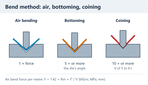
Bend method, under Selected step, presses a step into the die instead of air bending it:
- Air bending: the default.
- Bottoming: the sheet, pressed onto the die's flanks, takes the die's angle; 5 times the force of an air bend or more.
- Coining: the punch tip is pressed into the sheet, in a V of 5 to 6 t; 10 times the force or more.
These are S. D. Benson's factors (The Fabricator); a hem's flattening and an offset hit have their own. The force check and Auto take that force; the checks say when the die's angle is not the bend's (bottoming), or the V is too wide or the punch tip is not the bend's radius (coining).
Bump bending#
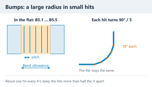
Bump bending makes a radius too large to air bend in one hit (Not checked: large-radius bend ...) as a row of small hits.
Set Bumps under Selected step to the number of hits, 2 to 40 (0 or 1: one hit). The hits B5.1, B5.2… lie at equal pitch across the bend's allowance in the flat, which stays the same, each turning its share of the angle round the part's rule radius; each is a step with its own X and a bend of its own in every file. The bend's pre-bend and its own die and punch and bend method are dropped; a part turned front to back for the bend stays turned.
The hits are made from the end farthest from the back gauge toward it, all of them against the same side: the sheet between the punch and the fingers stays flat and rests on the fingers, the bent part of the radius comes out in front, and X gets shorter hit by hit. The side is the one the gauge takes for the bend in one hit. Turn front to back on the bend or on any of its hits turns the whole series: its hits are then made from the other end. Play all steps slides the part over to the next hit's X, as the operator does.
The pitch, the allowance divided by the number of hits, plus the small bend deduction of a hit, must be at least half the die's V, or the sheet between two hits falls into the die (an ERROR: ... 0.5 V between two bumps). The error says what to change: At most 6 bumps fit on this die; or use a narrower die, or a narrower die when even two hits are too close. With a die near 8 t, that is about one hit every 4 t, rounded down: R40 at 90° in 2.5 mm sheet, an allowance of about 65 mm, takes 6 hits on a V20 die, about 11 mm apart.
A bend that one hit makes, its radius no larger than the rule's, needs no bumps: its allowance is a few millimetres, so on a usual die two or more hits fall into the die. The error then says B5 needs no bumps ... Set Bumps to 0.
Offset hits#
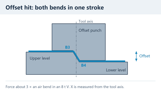
An offset hit makes both bends of a short offset (a joggle or a Z) in one stroke of an offset punch and die (see Offset tools).
Select the first bend's row and click Make an offset hit (Selected step): that bend sits on the top of the die's step, the side beyond it on the upper level, and the side beyond the other bend is pressed down onto the lower level. Select the other bend first for the other way round.
The other bend is the nearest parallel one that turns the other way by the same angle (90° at most), with no bend between and a flat web between their bend zones; neither may be pre-bent or in another offset hit. When there is none, the message says B3: no bend beside it turns back by its angle, ...
The step then reads B3, offset with B4; B4's own die and punch, placement and bend method are dropped. X is measured from the tool axis, over the middle of the web; the force is three times an air bend in an 8 t V (Mate: more than twice a single bend's).
Offset tools#
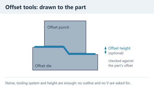
An offset hit needs an offset punch and an offset die, which the starter library and the catalogue do not have. To add them in Press Brake Library:
- Under Punches, pick + New entry with Style Offset; under Dies, + New entry with Type Offset.
- Give each its name and tooling system: each hit draws the tools to the part's offset, so no outline and no V opening are asked for.
Left empty, a punch's Body width is drawn 40 mm and its Height is saved as 100 mm; a die's Body width and Height are drawn 60 mm. Offset height (offset tools) and Angle (0 on a new offset entry) are checked against the part only when you enter them.
3D view of a step#
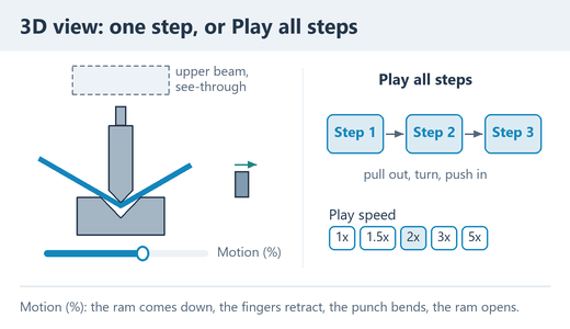
The 3D view group shows the step selected in the bend table beside the model, as the brake makes it.
| Control | What it does |
|---|---|
| Show the selected step in 3D | The part refolded to that point of the stroke, with the punch, die, back-gauge fingers and the machine's table along their lengths, the upper beam see-through, and the side frames see-through where the part reaches past them. Left on, the next Bend Sheet opens with it on. |
| Motion (%) | Runs one press cycle as the controller does: at 0 % the part lies on the die against the fingers with the ram open; the ram comes down to the part, the back gauge retracts as the punch pinches it, the punch bends the part (an air bend past its angle by its springback), the bend opens back as the ram lifts, then the ram goes back up to the step's opening (at least 5 mm above the part, so the next part of the run comes in under it; in a spring hemming die, above the part and the pad as its springs lift them off its body, which stays on the table). Where the part cuts into a tool, the volume they share is solid red and the tool see-through red. |
| Go to the contact | Shown when the step has a contact: returns to it. The view opens there, at the 3D check's first contact when it has run, else the section check's. |
| Play all steps | Every step in turn from step 1. Between two steps the ram stays open, going from the opening the step left it at to the one the next step starts from (higher while a part that must be set down over the die comes in); the part is lifted out of the die, pulled straight out, turned or flipped as the next step needs and pushed straight back to the gauge (a hem slides out of and into a spring hemming die's jaw at the jaw's height), and the fingers move over to the next X while it is out. When the next step takes the part as it lies (the hits of a bump series), it is slid over to that X instead, lifted only out of the V. After a tool change, the next step's tools show once the part is out, the ram at the top of its stroke. A part the ram does not open far enough to pull out straight (taken out tilted) is not turned: the step stays shown until the next one plays. Click Stop, or anything else in the dialog, to stop. |
| Play speed | 1x to 5x, also while it plays; remembered. |
The lines under the view give, from the top:
- where the stroke is: Step 2 (B2): bending, 45° of 91.5° (it opens about 1.5° when the ram lifts). (or the ram coming down to the part, the punch pushing the part and the die's pad down in a spring hemming die, back gauge retracting, springing back as the ram lifts, the ram going back up to its opening);
- in red, what touches there: In contact here (red): ...;
- Section check: ...: the step's first contact and its angle, clear (sampled) or incomplete;
- Light contact (the sheet's skin only, it may mark the part): ... when there are only those;
- No outline in the library, not drawn: ... and Approximate outlines: ...;
- in italics, what is drawn.
When the flat cannot be refolded (a bend not joined to its flanges in the flat), the view sweeps the section across the bend along it, with the formed end walls of a box. Nothing is added to the design: the graphics go and the camera returns when you untick the box or close the dialog.
3D check#
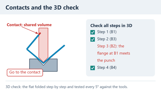
Check all steps in 3D folds the real part step by step, in the order of the table, and tests it against the punch, die, upper beam and the machine's table as solids, and against its side frames (solid behind their throat) and the back gauge's fingers, retracted as they stand during the bend, where the library gives them. The step stands where Tool setup on the bed puts its station.
A contact is more than 1 mm³ shared with a tool and more than a skin: a sheet lying on a long die only touches it. The 3D check sees what the section check approximates or leaves out (the real bend zones and corners, holes, forms on the walls, bend lines that stop short of the edges, the frames), but not the bend zone being formed, which the section check covers.
- A step takes a few seconds, with progress and Cancel. The bend motion has a 20-second limit; removal has up to 8 seconds per step. Auto divides its remaining total budget between the remaining steps. A check that runs out of time is left incomplete, as is a step with a tool that has no outline, a hem made in one hit, a teardrop or no V die.
- Constant-section parts are checked too, including taking them out beside other tool stations. While the dialog is open, results can be reused for the same formed bends, placement, tools and station layout. A changed shared setup needs a new check.
- Each contact is listed in the checks (Step 5 (B3), 3D check: the flange at B6 meets the punch at the start of the bend; a form is named: the louver 8c4508 meets the die) and printed as 3D check on the bend sheet. A new order or another tool clears the result.
- When the flat cannot be cut into its panels, the line under the button reads 3D check not available: ... with the reason (bends not joined in the flat: B2); the section check still covers the part.
How the section check works#
The section check runs on every plan after every change: it moves each step's cross-section through the stroke against the punch, die, upper beam, back-gauge finger and the machine's table under the die. The sheet bears on the die's shoulders as round as its Shoulder radius (sharp edges when it is not given).
The cross-section through the middle of the bend has the sheet's thickness. Each bend has its own inside radius, read from its zone in Fusion's flat pattern with the K-factor of the part's rule: check by hand a bend that unfolds with another K-factor. A bend whose zone cannot be read takes the rule radius.
The rest of the folded part goes with it: every panel and bend formed before, at any angle (a box's end walls and their returns, a flange along part of an edge, an oblique flange), and the forms on the flanges. Each piece is checked against the upper beam along the whole bend line, and against the punch, with its horns, and the die over their stations.
| What it finds | Result |
|---|---|
| A tool in the section, or in a folded piece's mid-surface | A contact, an ERROR: Step 3 (B1): The flange at B2 meets the beam during the bend at 47 deg. At the punch nose and the die shoulders, which bear on the sheet by design, only a cut into the sheet's mid-surface counts. |
| A station that does not fit between the bends formed at its ends | A contact before the bend starts. |
| A tool only in the sheet's skin (half its thickness, 1 mm at most) while the part moves | A light contact, a CHECK: the sheet gives that much, but may be marked (... the part touches the die lightly during the bend at 30 deg ...). Auto prefers a plan without one. Deeper, or with the part at rest on the die, it is a contact. |
| Something it cannot reach | Incomplete; Not checked says what (see When a check fails). |
Taking the part out with the ram open is checked first on the section, then as a sampled 3D route when the 3D check runs (Taking the part out). A complete loading route for putting the part in is not checked.
Outputs: PDF, DXF and CSV#
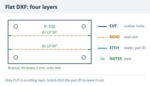
OK writes the files ticked under Outputs, for the selected part or every part, into the folder you choose (the folder dialog opens on the one chosen last; the ticks are remembered too). Apply the die's bend rule to the flat first, shown and ticked when a part's flat differs from its die and punch, applies their rule before (see Write the shop files); the message after OK names a part that could not be planned (Not included: ...).
| Output | File, named after the part (all parts: the design) |
|---|---|
| Bend sheet PDF | Bracket - Bend
Sheet.pdf |
| Flat DXF (CUT, BEND, ETCH, NOTES) | Bracket -
Flat.dxf, one per part, named after that part |
| Bend program CSV | Bracket - Bend
Program.csv |
| Always | Bracket - Bend Sheet.manifest.json: the
files written together, each with its checksum; keep it with
them |
The Bend sheet PDF starts each part on a new page (PART 2 / 5), under a header with the design, the date, the number of parts and bends, and the page number:
| Part | What it shows |
|---|---|
| Part block | Material, thickness, die (V, angle), punch (tip radius R, height H), machine (with its controller, and Starter library: the maker's data, not checked against your machine for a starter machine that keeps its published values: not once you give it values of your own), units, flat size, bends with the time a part takes (Time per part); DIE and PUNCH read Per step (see Tools by step) when the steps use different tools. |
| 3D VIEW | The folded part as Fusion draws it. |
| FLAT PATTERN | The flat seen from its top face with its overall size, each bend line with its name and steps (DOWN 90° · steps 1, 3 for a pre-bent bend), UP in blue, DOWN in red. |
| BEND TABLE | One row per step: STEP, BEND, DIR, ANGLE with the step's note, Ri, LENGTH, FLANGES (the finished part's outside lengths to the next bend or the edge, gauge side / front), X, DEPTH (Depth and opening), GAUGE, HANDLING, FORCE (kN). |
| TOOLS BY STEP | Each step's punch and die with their station, the CNC ANGLE (the angle as the controller takes it), the back gauge's fingers (R and Z), the OPENING, and its section check: Clear (sampled), Interference, Incomplete or Not checked, with light contact when a tool only touched the sheet's skin. |
| TOOL SETUP ON THE BED | For a part that takes two or more punch and die sets, or shares the bed with other parts: each station, its shut height and where it stands on the bed, with its setup and the parts it serves (Tool setup on the bed). |
| CHECKS | Tool search: and 3D check: when they ran, the ERROR: and CHECK: lines, then Not checked:, Machine values not given (these checks are off): with the values only, and Assumed:. |
| SIDE VIEWS | The part on the die before each bend, the back gauge on the right, with the section check under each view (sampled clear, incomplete, collision: punch at 47°, drawn in red). |
The Flat DXF (CUT, BEND, ETCH, NOTES) is R12 in millimetres (inches for an inch design), seen from the top face like the PDF's flat, the longer side along X. Cut it as drawn, not mirrored, so the face up on the table is the top face, the one UP bends fold toward. Forms made by this add-in are not in it (see Parts with forms and bends).
| Layer | What it holds |
|---|---|
CUT | The outline and the holes: the only layer to cut. |
BEND | The bend lines, dash-dot
(CENTER). |
ETCH | A 3 mm mark at both ends of each bend line and the part ID, 5 mm high in a single-line font: lines only, for a plasma scriber or a laser. |
NOTES | A text such as B1 UP 90° along each bend line, and a title under the part: its name, thickness and units. |
The part ID is the component's Part Number, else its name; untick Etch the part ID in the DXF to leave it out. It goes as near the middle as it fits 2 mm clear of the edges, holes and bend lines; where nothing fits, at the lower-left corner of the flat's bounding box, 2 mm in, where it may cross a hole, a bend line or the edge: check it there.
The Bend program CSV has one row per step of every part, to type into the brake controller:
| Column | What it holds |
|---|---|
Part, Step, Angle (deg),
Direction, Die, Punch,
Gauge, Handling, Force (kN),
Punch station, Die station | As on the bend sheet, each step with its own tools. |
Bend | The bend with the step's note (B5.7 bump 1 of 7: the hit B5.7, made first; B3 offset with B4). |
Angle on the controller (deg) | The angle to
type: between the flanges by default (135 for a bend that turns
45°; empty for a hem or a closing pressed flat, set by its ram stop,
but 0 on an ESA), as the machine's Angle on the
controller says; Angle (deg) is how far the flange
turns. |
X (mm) or X (in) | Empty for a step that finishes a pre-bend. |
Problems | The step's ERROR and CHECK messages
and those about its bend, on a part's first row also those about the
whole part, separated by |. |
Depth, Y, R,
Z1, Z2, Z from,
Opening, Opening from, Opening
tilted | The punch depth, the ram's Y, the fingers' R and Z and the ram opening after the step (straight out, and tilted out when that takes less), in your machine's coordinates where its library entry gives them (Your machine's coordinates, Depth and opening, Back gauge). |
Bed station | For a part with two or more punch and die sets, or set up with other parts: the step's station and where it stands on the bed, with its setup when there are more (Tool setup on the bed). |
Time (s) | About how long the step takes with its handling (Time per part). |
While the files are written:
| The dialog says | What to do |
|---|---|
| These files already exist and will be replaced: ... Continue? | Yes replaces them; No writes nothing. |
| An older companion would be left beside the new revision: ... Choose a new file name, or move that file out of the folder. | An earlier bend sheet in this folder wrote a file this one would not, such as a DXF you have unticked (its manifest says so). Bend Sheet asks for no file name: tick that output again, move the old file out, or choose another folder. |
| Package was not published; previous outputs were restored: ... | Writing failed: the folder keeps the files it had. |
What Bend Sheet keeps#
Bend Sheet keeps the plan on each part's component when it writes the files; save the design to keep it. It stores the machine, material, die and punch, the bend order with its pre-bends and offset hits, the bumps, and each step's own die and punch, gauge side (Turn front to back) and Bend method.
The next Bend Sheet of the part starts from them (the order while the part has the same bends); a part without a setup starts from the machine, material and punch used last: those of the last files written or bend rule applied, or the machine and material you last picked in Bend Sheet or Apply Bend Rule (see Apply Bend Rule). A machine nobody chose (the starter library's first) does not replace one you picked on another part, also when several parts are written at once. A machine, material, die or punch it was planned with that is not available now (deleted from the library, or not for the machine) is replaced, and the dialog says which in orange at the top. When the plan cannot be stored on the component, the closing message says so: while Fusion runs, the next Bend Sheet of the part still starts from the plan written. The 3D check's result is not kept; the bend sheet prints it.
Until the files are written, while Fusion runs, the plan you change in the dialog (or Auto plans) is kept through Cancel, in the dialog or in the folder dialog, and through No in the replace question: the next Bend Sheet of the part starts from it, unless a bend sheet or a bend rule was written for the part since. A copy of the design (a Data Panel copy, Save As) does not take it. Closing Fusion drops it, and so does the first save of a new design; write the files to keep it with the part. A machine nobody chose (the starter library's first) is not kept as the part's.
Bend Sheet also remembers for the next time the Parts choice, the ticks under Outputs, Show the selected step in 3D, the Play speed and the folder last chosen.
Forms#
The add-in makes ten form types on a Fusion sheet-metal part: louvers, lances, bridges, dimples, embosses, debosses, knockouts, extruded holes, beads and gussets. Five commands work with them: Create Form, the Forming Tool Library, Tab and Slot (Tab and Slot joints), Audit Forms and Manufacturing Export.
Parts with forms and bends#
A part with forms is cut and formed flat, then bent. Work in this order:
- Model the part with Fusion's sheet-metal tools, finish its flanges and cut-outs, and apply your brake's bend rule now (Apply Bend Rule): the blank is cut from this flat pattern.
- Add the joints with Tab and Slot and the forms with Create Form.
- Run Audit Forms and fix its errors.
- Run Manufacturing Export; cut and form the blank from its CUT/FORM DXF and handoff PDF (The handoff sheets and the CUT/FORM DXF).
- Run Bend Sheet for the press brake; it checks the forms against the tools (Forms near a bend). If you accept another bend rule there, the flat pattern changes: export again.
Before creating a form#
Create Form needs a few things in place; check them before your first form.
- Finish the native flanges and cut-outs first: features of your own after the forms stop Edit existing form from changing or deleting them. Tab and Slot joints can be added or edited later (Tab and Slot joints).
- Plan the components: forms go on one body per component, the one its flat pattern is made from, and a Tab and Slot joint needs both its sheets in one component.
- Use a planar or cylindrical face: louvers, bridges and lances need a planar one (a rolled part is punched flat, then rolled); a gusset across a bend takes the bend's own face.
- On a cylinder, have a vertex, sketch point or construction point on the cylindrical face to measure the forms from (Placing a form).
Forms are modelled in the folded part after the flat pattern, and reach the shop through Manufacturing Export, not through Fusion's flat pattern. Without a flat pattern, Create Form makes one from the face you pick or the largest planar face, and stops before adding anything if Fusion cannot; a sheet with no planar face (a rolled cylinder) needs its Fusion flat pattern first.
| The dialog says | What to do |
|---|---|
| Sheet Metal & Press Brake requires a parametric Fusion design | Work in a Part or Hybrid design that captures design history. |
| … Assembly intent is not a modeling target. | Open the part's own design. |
| Edit the owning component before creating a form… | Activate the sheet-metal component you change. |
| Select the folded-model face… | Pick faces of the folded sheet-metal body, not in the Flat Pattern; on any other body OK stays grey. |
| The component flat pattern belongs to another sheet-metal body | Give this body a component of its own: right-click it in the browser, Create Components from Bodies. |
Create Form#
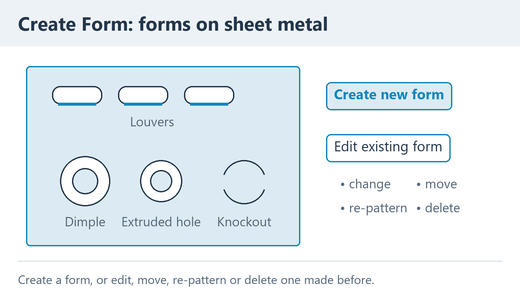
Create Form places a form, or a pattern of forms, on a sheet face; the same dialog changes, moves and deletes forms (Edit existing form). For a first form:
- Open Create Form; Operation is Create new form.
- Under Placement, click the sheet face and set X, Y and Rotation (Placing a form).
- Choose the Form type and a shop tool under Tool (Forming Tool Library), or keep Custom size and type the sizes (Form types and sizes).
- To repeat the form, open Placement pattern (Placement pattern).
- Read the Checks box (Checks: tool makers' limits); tick Show the forming tool to see the punch and die (Show the forming tool).
- Click OK.
Sizes, spacings and pitches are in millimetres, also in an inch design;
to enter inches, type the unit, for example 0.25 in.
The dialog opens with the form type you last created, each type with the sizes, tool code and tool you last used for it on this computer (the tool while the Tool list has it). For production forms, see Engineering qualification.
Placing a form#
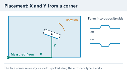
The Placement group sets where the form goes and which way it points.
| Option | What it does |
|---|---|
| Target sheet face | The form goes where you click. A planar sheet face selected before you open Create Form gets the form at its middle. |
| Measured from | On a planar face, where X and Y start: the face corner nearest the click, or a vertex, sketch point or construction point you pick (the form stays where it is). |
| X, Y | The form's centre from that point, X first, Y from the end of X: type them or drag their arrows. |
| Curved coordinate-zero reference | On a cylindrical face (no X and Y): the zero of every form there, a vertex, sketch point or construction point on it. The centre is the click, X its developed arc length from the zero, Y along the axis; without a zero, each form is measured from its own click. Later forms with the same Actual fixture datum ID reuse and check the zero. |
| Rotation | Turns the form about the face normal; at 0° its Length runs along the X arrow's line. |
| Form into opposite side | Makes the form toward the sheet's other side; otherwise a form rises out of the face you pick and a deboss sinks into it. |
The preview shows every form of the pattern as the tool leaves it, the lanced edges (a louver's open front) in dark lines; on a cylindrical face, their outlines.
A form whose tool footprint overlaps another form's is refused in the Checks box: … have overlapping forming-tool footprints on the same sheet support. Move, resize, or remove one form.
Form types and sizes#
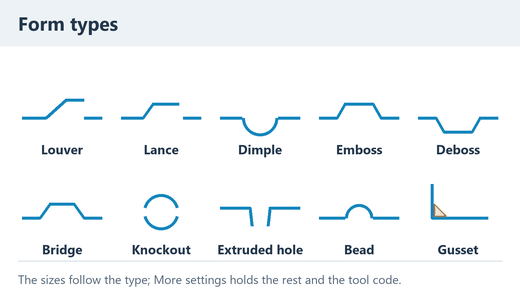
Each Form type has its main sizes under Form dimensions, the rest and the Tool / punch code under More settings. Its sheet range, smallest sizes and refusals are in Checks: tool makers' limits.
| Form type | Sizes | Notes |
|---|---|---|
| Louver | Width, Length,
Height More settings: End radius (the drawn ends), Form angle (45°), Ends, Made by, Tool length, Step per hit | Lanced along its front; the hood rises from its back at the Form angle. |
| Lance | Width, Length,
Height More settings: Bend angle (the ramp's, 30°) | Cut on three sides, lifted by a ramp at its root; the free end draws back by Height × tan(ramp angle / 2). |
| Bridge | Width, Length,
Height More settings: Crown corner radius (the strip's corners) | Lanced along both long sides, lifted by a ramp at each end. |
| Dimple | Diameter (at the base),
Depth More settings: Draft angle (30°) | A round drawn form. |
| Emboss | Width, Length,
Depth More settings: Corner radius, Draft angle (30°) | A rectangular form raised out of the face, with drafted walls and rounded corners. |
| Deboss | As an emboss | The same, sunk into the face. |
| Knockout | Diameter (the hole), Trade
size More settings: Cut clearance (the ring's gap), Tab width and Tab count (the ties) | A slug in a cut ring, held by ties until it is knocked out. |
| Extruded Hole | Thread, Hole diameter
(the bore), Extrusion height (above the sheet face) More settings: Pre-hole diameter, Flange diameter (the collar's outside) | A hole with a drawn collar, for a thread or a spacer. With Pre-hole diameter 0 it is pierced and drawn in one hit. |
| Bead | Width, Length, Depth,
Made by, Bead path More settings: End radius, Step per hit, Smallest path radius | A stiffening bead with round ends, straight or along a path (Beads along a path and gussets across a bend). |
| Gusset | Placed, Width, Length,
Height More settings: Corner radius | A stiffening rib: a raised, rounded triangle on a flat face, or a rib in the inside of a bend. |
Louvers, bridges and lances are one sheet thick with every lanced edge open, as the punch-press tool makes them. Height is top to top; a louver's front opens over the height less one thickness. On a wall, turn a louver with Rotation so its front faces down.
A louver's Ends are Closed (drawn), or Open (lanced): cut along the front and both ends, only the back bent, for more air on inside panels (Mate). Made by:
- Punch press, one hit: a tool as long as the louver;
- Punch press, progressive: a shorter tool steps along it from the middle out, for any length; give its Tool length and Step per hit;
- Press brake louver die: the slit is cut first, then the die forms it (Protocase).
For a dimple, emboss or deboss the sizes give the base; the Draft angle is the wall's angle from vertical, so the crown is smaller by Depth × tan(Draft angle) on each side.
Trade size fills in a knockout for the sheet: the NEMA 71 hole of a conduit size (1/2 to 4 in) or cable gland (M12 to M63), with the ties and gap tool makers use. Typing a Diameter picks the matching size, or Custom.
An extruded hole's Thread (M3 to M10 or #6-32 to #10-32, thread forming or thread cutting) fills in the bore and pre-hole from Mate's table, the collar for a 0.6 t wall (TRUMPF) and a height of one thickness. The model has no thread.
A form is the shape the tool leaves: no forming strain, thinning or springback. On a cylinder Fusion decides how the shape wraps onto the face, so qualifying a cylindrical process includes measuring the result in Fusion.
Placement pattern#
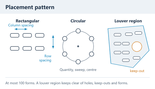
Placement pattern repeats the form. The placed form is the pattern's first, and the whole pattern is one form, edited or deleted together. One OK makes at most 100 forms; for more, make several patterns.
| Option | What it does |
|---|---|
| Pattern | Single, Rectangular, Circular or Louver region (Fill a louver region). |
| Columns, Column spacing | Rectangular: the forms along the Pattern axis and their spacing (negative: the other way). |
| Rows, Row spacing | Rectangular: the same at 90° to the axis; one row makes a line. |
| Pattern axis | Rectangular: the columns' direction; 0° is the X arrow's line. |
| Quantity | Circular: the forms, the placed one included. |
| Center offset X, Center offset Y | Circular: the centre, from the placed form and not on it (Circular pattern center must be offset from the selected seed.). |
| Sweep | Circular: the angle the forms spread over; 360° is a full circle. |
| Include end position | Circular, under 360°: the last form at the end of the sweep (refused on a full circle). |
| Rotate each form | Circular: turns each form with its place on the circle. |
The spacings and the centre offset follow the face's own directions, which can be opposite to the X and Y arrows: check the preview.
Forms of the pattern whose tool footprints overlap are refused: … overlapping forming-tool footprints. Increase the pattern spacing or split the layout.
Fill a louver region#
A louver region fills a closed sketch profile with louvers on a grid, clear of the holes, the other forms and the keep-outs you choose.
- Sketch the region, and any keep-outs, as closed profiles on the plane of the louver's face, in the sheet's component, before the first form in the timeline.
- In Create Form, place the first louver in the region, or select a louver made before with Edit existing form, and set Pattern to Louver region.
- Select the profiles and set the grid (table below).
- Click OK: it makes the first louver and fills the region around it. The preview shows the first louver only.
| Option | What it does |
|---|---|
| Fill region | The closed sketch profile to fill. A louver is kept, the first one too, only where its whole tool footprint is in it and on the sheet. |
| Keep-out regions | Closed profiles to keep clear of (optional). |
| Column pitch, Row pitch | The grid's steps from the placed louver, along the grid angle and across it: each larger than a louver's tool footprint, and not under the tool's Minimum form pitch (mm). |
| Boundary clearance | The room each tool footprint keeps from the region's and the sheet's edges, the holes, the keep-outs and the other forms; a tool's Minimum edge distance (mm) raises it. |
| Grid angle | Turns the grid (0°: the X arrow's line), not the louvers: they keep the first louver's Rotation. |
| Clear saved keep-outs | Opened again, a louver shows its pitches, clearance and grid angle, but uses its saved profiles, with Fill region and Keep-out regions empty. Select a profile to replace them (a deleted one must be selected again), or tick this to drop the saved keep-outs. |
The fill stops, with its reason, when:
- a sketch is after the first form in the timeline, or off the louver's plane;
- a pitch is not larger than the footprint, or no louver fits;
- it needs over 100 louvers or 25,000 grid places: increase the pitches or split the region;
- the component has other forms on a cylindrical face (a gusset across a bend is no obstacle).
The louvers do not follow later edits of the sketches or of other forms. To rebuild them, choose Edit existing form, select a louver and click OK; until then Audit Forms reports the region as changed (… Rebuild the louver (Create Form, Edit existing form, OK) …). A rebuild keeps the instance IDs of the grid places that stay.
Beads along a path and gussets across a bend#
A bead can follow a sketch path, and a gusset can sit across a bend; each is one form, with no Pattern. A bead's Made by:
- Punch press, one hit: a bead tool as long as the bead;
- Punch press, nibbled: hit by hit, at the Step per hit (about 0.8 mm);
- Rolled (wheel tool): give the wheel's Smallest path radius (TRUMPF 30 mm, Mate 16-20 mm);
- Press brake rib die: one stroke.
Without a Bead path the bead is straight, centred where you place it. A nibbled or rolled bead can follow one: sketch lines, arcs and circles on its planar face, end to end, with corners rounded by arcs of at least half the bead's width (a closed path makes a ring).
The bead then starts at the path's start and runs its length, with round ends (Length, X and Y are hidden); it does not follow later edits of the sketch.
A gusset Placed Across a bend (press brake) is a rib pressed into the inside of the bend in the bend stroke, with gusset tooling (TRUMPF), or after bending. Click the bend's face, inside or outside, where the rib goes. Length is each leg along the flanges from the inside corner, Width the rib's width; the bend sets the rest, so Rotation, Height and Corner radius are hidden.
The bend must be 15° to 165°, the rib within the bend's length and the legs past the bend, on the flanges; the message says what to change.
The rib is a separate body: the sheet body and its flat pattern do not change. For its tooling, see Forms near a bend; the punch-press handoff leaves it out, and the Punch Map lists it without handoff coordinates.
Show the forming tool#
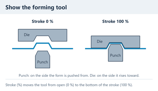
Show the forming tool draws the punch and die of the pattern's first form on the face. They are made from the form's own shape, without the tool holder, stripper and springs. The switch is off when the dialog opens, and hidden on a cylindrical face, for a gusset across a bend and for a bead along a path.
- The punch stands on the side the form is pushed from; the die, with the form's cavity, on the side it rises toward.
- Where the tool shears the sheet (a louver's, lance's or bridge's lanced edges; a knockout's ring), the punch edge stands on the cut and the die edge one cutting clearance (0.1 × thickness) outside it. Drawn walls keep one sheet thickness between punch and die.
- A knockout punch is relieved at its ties. An extruded hole's punch has a nose for the pre-hole; without one it is Mate's one-hit pierce-and-extrude tool. A progressive louver shows one hit of its shorter tool, in a die channel open at both ends.
Stroke (%), shown with the tool, moves it from open (0 %) to the bottom of the stroke (100 %): the die on the sheet, the punch in the form as it leaves it (a knockout's slug pushed about 1.1 × thickness).
Checks: tool makers' limits#
The Checks box shows, while you edit a form, what tool makers publish for it: up to six CHECK lines and how many more, or No problems found. These are warnings: OK still makes the form, and a shop with other tooling may make it.
The findings are saved with the form, with no message after OK:
Edit existing form shows them again,
Audit Forms measures them again and the Punch
Map of Manufacturing Export lists them
in shop_checks.
A red Cannot create: line is a refusal: the add-in cannot model the form that way, its tool overlaps another form, the face does not suit it, a form has no sheet under its centre (Form 2 of 3 has no sheet under its centre...: it lies over a hole, a cut-out or past the sheet's edge; move it or change the pattern), or the pre-check of Engineering qualification is blocked (before you pick a face, it asks for one). OK is then greyed, or refuses the form with the same reason.
A reason names a size as the record does: dimensions.width
is Width, dimensions.draft_angle Draft angle,
sheetThicknessMm the sheet.
Each form type is refused outside its sheet range and under its smallest main size (t is the sheet thickness):
| Form type | Sheet | Smallest main size |
|---|---|---|
| Louver, Lance, Bridge | 0.4–3 mm | Width 3 t, Height 1.5 t |
| Dimple | 0.4–4 mm | Diameter 3 t |
| Emboss, Deboss, Bead | 0.3–3 mm | Width 3 t |
| Knockout | 0.4–3 mm | Diameter 4 t |
| Extruded Hole | 0.4–4 mm | Hole diameter 2 t, unless it has a Pre-hole diameter |
| Gusset | 0.5–6 mm | Width 2.5 t |
Sizes that do not fit together are refused too: a width over the length, a radius over half the width, a louver, lance or bridge with no room for its crown or opening, a dimple, emboss or deboss whose draft leaves a crown under 2.2 t.
The warnings, with their sources:
- Punch-press reach: about 6.5 mm high for louvers, beads, dimples, embosses and debosses (Mate, AMADA), 4 mm for dimples, embosses and debosses with a wall under 45° (AMADA), 6.4 mm for lances and bridges (Mate); higher needs an upforming station or a press-brake die. Louvers and beads made on a press brake are exempt.
- Louvers: height about 4 t in mild steel, 3.5 t in stainless steel and aluminium (Conic); width at least twice the height, or the form draws back; form angle at least 40°, 45° preferred (Wilson); made progressive, a Tool length and a Step per hit of at most t (Wilson; Mate 0.8 mm), the tool shorter than the louver (else one hit).
- Lances: height 4 t. Bridges: 3 to 5 t by ramp angle (Conic).
- Dimples, embosses and debosses: depth 3 t, 4 t for a dimple with a wall from 45° (AMADA, Conic), and at most 0.3 × the diameter or width (AMADA); walls at least 30° from vertical, the default (AMADA); an emboss or deboss corner radius at least its depth (AMADA); sheet up to 2 mm, 1.5 mm stainless (AMADA).
- Beads: depth 3 t and 0.4 × the width (Mate, AMADA); nibbled, a Step per hit; rolled, a Smallest path radius, a path no tighter, and sheet up to 2 mm steel, 1.5 mm stainless, 2.5 mm aluminium (TRUMPF, Mate).
- Extruded holes: 2.5 t high overall, from the far face (Mate; TRUMPF 2 t); a pre-hole at least t (Mate, AMADA) and smaller than the bore, and one for a collar wall thinner than the sheet; with a Thread, Mate's bore and a sheet no thicker than Mate makes that thread in (thicker sheet is drilled and tapped); sheet up to 2.7 mm, 1.5 mm stainless (Mate, AMADA).
- Knockouts: one tie up to 34.9 mm, two above (Mate); ties 2 t wide, warned under t or over 3 t (AMADA); a cut gap of at most 0.25 mm (NEMA 55); stainless up to 2 mm (AMADA).
- Gussets on a flat face: height 8 t.
- Distances on a planar face, from the form's outline (Mate): 3 t to a sheet edge or a cut-out, 6 t to another form, 3 t between louvers, 3 t + R to where a bend starts (R: its inside radius); a press-brake louver 15.88 mm from an edge or a bend (Protocase). None are measured on a cylindrical face.
The checks take the material from This part: material grade, else from Material grade (Engineering qualification), not from the part's Fusion material. A grade naming stainless steel (stainless, inox, 304, 316, 1.4301…) or aluminium (aluminium, 5052, 6061, AlMg3…) gets that material's limits; any other grade, or none, those of mild steel.
Edit existing form#
Edit existing form changes, moves, re-patterns or deletes a form made with Create Form. It rebuilds the form and every later form of the component in place in the timeline; the forms keep their IDs, and a failed rebuild puts them back as they were.
| To | Do this |
|---|---|
| Select a form | Choose Edit existing form under Operation and select a face of the form, or its timeline group, under Form; or select the form before you open Create Form. Its type, sizes, tool code, rotation, side, pattern, face, place and saved Checks fill in. |
| Change it | Change the values or the pattern and click OK. The preview shows the rebuilt form, except for a bead along a path or a gusset across a bend. |
| Move it | Change X and Y, drag their arrows, or pick another face of the same sheet body; click OK. |
| Delete it | Tick Delete this form, click OK and answer Yes to Delete this form definition and all geometry owned by it? This does not delete the baseline flat pattern. The later forms are rebuilt. |
A form keeps the evidence it was made with: the Engineering qualification group is hidden here, and a tool chosen in the Tool list only fills in its values (Engineering qualification).
| The dialog says | What to do |
|---|---|
| Edit cannot safely rebuild this form timeline suffix because downstream user features exist: … (or Delete cannot …), with their names | The add-in cannot rebuild features it did not make: drag them ahead of the form's group, or delete them and add them again afterwards, then try again. |
| A qualified form cannot be rehosted onto a different sheet face… | A form with Vendor specified or Shop qualified evidence stays on its face: create a new form on the other face. |
| A bead along a path keeps its path: delete it and create it again on the new face. | Do so: here a path bead changes only its sizes. |
| A form with a locked cylindrical datum cannot be … | A form measured from a cylindrical fixture datum stays on its cylinder: delete it and create it again there. |
| Move / repair must stay on the same resolved sheet body… | No form leaves its sheet body: delete it and create it again on the other body. |
Engineering qualification#
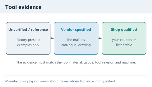
The Engineering qualification group records what a forming tool's data rests on, and so whether Manufacturing Export counts a form as made with qualified tooling.
Fill it in for a tool in the Forming Tool Library. In Create Form, where it is closed at first, a library tool fills it and you confirm the part and press; for a reference form, leave it as it is.
| Level | What it means | What it needs |
|---|---|---|
| Unverified / reference | No evidence: the default, and the factory presets. | Nothing. |
| Vendor specified | The tool maker's catalogue or drawing. | Tool manufacturer, Supplier / shop tool ID, Tool revision, Source document, Material grade, Qualified thickness min (mm) and Qualified thickness max (mm). |
| Shop qualified | A part your shop made with the tool and accepted: a test coupon or first article. | The same, and Press / machine. |
Until those fields are filled, OK (Save Tool in the library) is
greyed and the pre-check reads A qualified tool profile requires:
…, naming the fields as the library file does
(toolId, sourceDocument,
thicknessMinMm/thicknessMaxMm…).
| Option | What it does |
|---|---|
| Manufacturing sequence | Reference geometry only (the default: a reference form, whatever its evidence), Form on flat blank, then bend / roll, or Form after rolling on matched cylindrical die: Shop qualified only, for a cylindrical face, with Qualified support surfaces at Cylindrical only, a Matched support radius (mm), Radius tolerance (+/- mm), Radius refers to (the surface it is measured on), Support-die contact and Fixture datum ID. |
| Qualified support surfaces | Planar only, Cylindrical only or Planar + cylindrical: a qualified tool refuses a face of another kind (The selected planar face is not included in this qualified tool profile.). |
| Minimum edge distance (mm), Minimum bend distance (mm), Minimum form pitch (mm), Grain direction rule | Each adds a check you confirm for the part (below). The edge distance and the pitch also bound a louver region (Fill a louver region). |
| Source page / section, Material condition, Punch radius (mm), Die radius (mm), Die clearance (mm), Qualification notes | Recorded with the tool. |
With Vendor specified or Shop qualified evidence and a sequence other than Reference geometry only, Create Form shows Actual workpiece and press setup, what this job really uses: type each value as the tool has it and tick what you checked.
| When | Type | Then tick |
|---|---|---|
| Always | This part: material grade; This part: material condition when the tool gives one | Material checked against drawing / certificate, Installed tool ID and revision checked |
| Shop qualified | This setup: press / machine | Machine identity checked |
| For each distance the tool gives | – | Minimum edge distance checked, Minimum bend distance checked, Minimum pitch to all existing forms checked |
| With a grain rule | This part: grain direction / orientation | Grain direction checked against the qualified rule |
| After rolling | Actual support-die radius (mm), within the tolerance; Actual radius refers to; Actual support-die contact; Actual fixture datum ID | Actual support-die radius measured / certificate checked, Actual fixture datum is available and checked |
A change clears the ticks that depend on it (another face, Evidence status, Manufacturing sequence or Qualified support surfaces clears them all): tick them again. Choosing a tool, or typing over its values, empties the whole actual setup.
The Manufacturing release pre-check line at the end of the group reads:
- REFERENCE ONLY: Unverified / reference evidence, or Reference geometry only. OK makes the form; Manufacturing Export lists it in its warning.
- BLOCKED, with what is missing: OK is greyed, and the Checks box reads Cannot create: Manufacturing release pre-check is blocked: …
- PRE-CHECK COMPLETE: your entries match the tool; OK still checks the geometry, thickness, face and pitch.
Manufacturing Export counts a form as qualified, and leaves it out of its warning, only when it was made with a Shop qualified tool from the Tool list of Create Form, with the pre-check complete, and neither the tool nor the form has changed since (Tool, part, pattern or setup data changed since qualification.).
A Vendor specified tool's forms stay in the warning until a part made with it passes a shop trial (Vendor data defines a tooling envelope, but no part made with this setup has been accepted yet…), and so does evidence typed into the group without a library tool (No technical fingerprint is bound to the qualification evidence.).
An edit keeps a form's evidence, so to clear the warning, delete the form and create it again with a Shop qualified tool (Tooling that is not qualified, and Reference-only). For a Vendor specified tool, once a part made with it is accepted, first save it as a new Shop qualified tool.
What is saved with a form#
Each form is one collapsed timeline group, named for its type and the end of its ID (FW | Louver | 1a2b3c4d), with a record on the sheet's component.
The record holds the type, sizes, face, place and pattern (or louver region, bead path or bend), the tool code and library tool, the evidence and actual setup the form was made with, and its Checks.
Forming Tool Library#
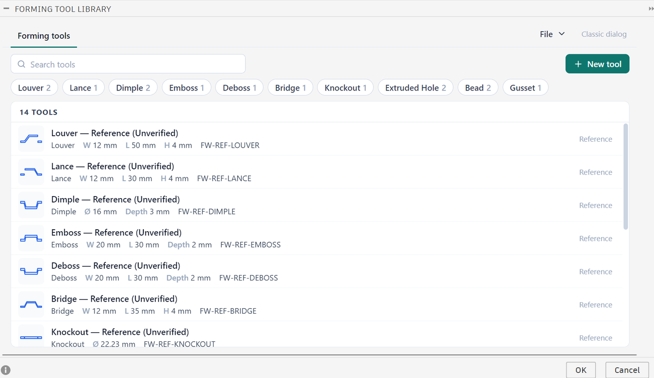
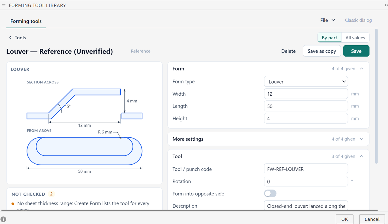
Forming Tool Library keeps your shop's forming tools for Create
Form to list: each a form type with its sizes, Tool / punch code,
rotation, side and the evidence it is qualified by
(Engineering qualification). They
are kept on this computer in tool-library.json
(About, updates and your
data).
The library opens as a page: the list of the tools, each with its section drawn small, its form type, main sizes and code, and its marks: Reference (a reference tool), Own (a tool of your own), Vendor specified or Shop qualified (its evidence), and Evidence for other values (see below). Type in the search box to find a tool by its name, code, maker, machine, material or description; a chip for each form type keeps only the tools of that type.
- Click a tool to open it, or + New tool for a new one.
- Choose its Form type and type its sizes; give it a name, the one Create Form lists it by, in the large box at the top.
- Click Save. Save as copy saves the values shown as a new tool and leaves the one opened as it was; Delete deletes it, after a question; Revert drops what you typed.
The values show in two arrangements, chosen at the top right:
- By part: the form is drawn in section and from above, from its sizes, beside the groups of its values. A size and its box light each other, and clicking a size takes you to its box; a size drawn dashed is one whose box holds no value that reads (the drawing takes the saved one). The groups are Form (its type and main sizes), More settings, Tool (code, rotation, side, description), Evidence, Tool limits, Curved support (only for a curved post-form) and Notes.
- All values: one table of every value; type in Find a value by its name to keep only those whose names hold the words.
- What a value is for is in its tooltip. A red * marks a value the tool needs, and a value that cannot be saved is marked under its box (Type a length, for example 12 or 0.5 in.); Save stays greyed until it is fixed. The card Not checked says what Create Form and Manufacturing Export leave out while a value is not given (no sheet thickness range: the tool is listed for every sheet), each line a link to its box.
Lengths are in the design's units; a value may say its own unit
(12 mm, 0.5 in). The library has no sheet, so
Thread and Trade size fill the sizes for a 1 mm sheet: set
the collar, height or tie width for the tool's gauge before you save. The
drawing shows the sheet at the tool's thinnest thickness, else 1 mm.
Saving. A tool is saved by its Save. Until then what you typed stays on the page while the dialog is open, and a bar at the bottom names each tool not saved yet, with Save all. The dialog's OK saves them all in one write, closes, and says what it saved; it is greyed while a tool typed in cannot be saved, and the bar says so. Cancel closes and drops what is not saved.
Evidence for other values. A Vendor specified or Shop qualified tool's evidence is bound to the values it was qualified with. Change a size, the code, the rotation or the side and save: the tool keeps its evidence for the old values, shows Evidence for other values, Create Form refuses it on OK (The sizes differ from the selected tool. Choose the tool again, or Custom size.) and the forms made with it read as not qualified in Manufacturing Export. Only when the tool as it is now was qualified (a new catalogue page, coupon or first article), tick Bind the evidence to these values under Evidence before you save. To keep both, use Save as copy.
The ten reference tools (Louver — Reference (Unverified) and
the like, codes FW-REF-...) are examples, not real tools, and
Create Form does not list them. To start a tool from one, open it and use
Save as copy, then rename the copy and save.
| File menu | What it does |
|---|---|
| Import… | Adds the tools of a library file: the page first says how many, and how many with the same ID it updates; a tool whose name another tool has is renamed … (Imported 2). |
| Export… | Writes the whole library to one file, to keep or to use on another computer. |
| Restore the reference tools… | Adds back the reference tools deleted and puts those changed back to their reference sizes, after a question; your own tools stay as they are. |
In Create Form the Tool list shows Custom size and the tools of the form type that fit the sheet (within the tool's qualified thickness range, or with none); before a face is picked, all tools of the type. A tool fills its sizes, code, rotation, side and Engineering qualification; typing over a size, the code, the rotation or the side goes back to Custom size and Unverified / reference.
If tool-library.json cannot be read, Create Form and Forming
Tool Library say so and use the reference tools for that session, without
changing the file. The library's first save, delete or import of that
session copies the file to
tool-library.unreadable-<date>-<time>.json in the
same folder, says where, then writes; if the copy fails, nothing is
written. Import your last export to get your tools back.
Tab and Slot joints#
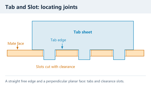
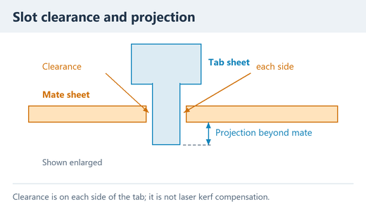
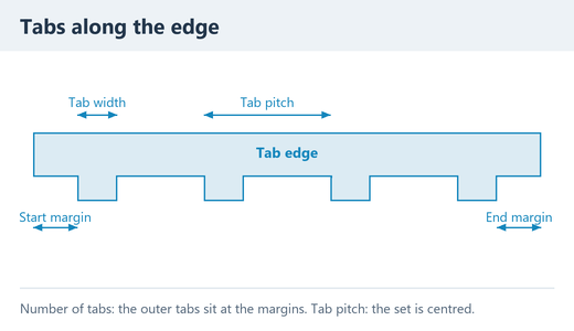
Tab and Slot puts locating tabs on one sheet's edge and cuts matching slots, with fit clearance, in the sheet it meets at a straight 90° joint. It needs a Part or Hybrid design with design history (Enable design history before creating an editable Tab & Slot joint.); in an Assembly design, open the part's own document.
What it joins: two sheet-metal bodies of the active component, or two walls of one folded body that meet at an open corner, picked on the folded model, not in the flat pattern; never sheets of different components.
- The tab edge is straight, with a square end, and parallel to the mate face.
- The mating sheet is 0 to 5 mm from it and does not overlap its end (Trim the corner before adding tabs.).
- Every tab lands on the mating sheet's material, not past it or in a hole.
- Activate the component that owns both sheets and open Tab and Slot; Operation is Create new joint.
- Select the Tab edge, a straight edge of the tab sheet's end that faces the other sheet, and the Mate face, the broad face of the other sheet that takes the slots.
- Set the spacing and sizes (below); the status line shows the tab count and both sheet thicknesses.
- Check the Preview and click Create Joint.
| Option | What it does |
|---|---|
| Spacing | Number of tabs (Tab count 1 to 50): the end tabs at the margins, the others evenly between, a single tab centred. Tab pitch: from the start of one tab to the start of the next; as many tabs as fit, centred between the margins. |
| Tab width | Each tab's width along the edge. |
| Start margin, End margin | From the two ends of the edge. Which end is the start follows the edge's direction in Fusion: check the preview when the margins differ. |
| Projection beyond mate | How far the tabs stand out past the mating sheet; 0 is flush with its far face. |
| Slot clearance (each side) | Above 0: how much larger each slot is than its tab on every side. Fit clearance, not laser kerf compensation. |
| Preview | Shows the tabs and slots; the original sheets stay hidden until Preview is off or you cancel. |
A new joint starts with the spacing, sizes and Preview setting of the last joint made or updated.
When the layout does not fit, the status line says why:
| The dialog says | What to do |
|---|---|
| The edge is too short for the tab width and margins | Smaller margins or a narrower tab: the edge must be longer than both margins and one tab. |
| pitch_mm must exceed tab_width_mm plus twice clearance_mm, Adjacent tabs must have a gap greater than twice clearance_mm | A larger Tab pitch, or fewer or narrower tabs: the gap between two tabs must be more than twice the slot clearance. |
| Clearance-expanded slots must stay within the source edge | Make each margin at least the slot clearance. |
| The requested tab extension is too long… | Less Projection beyond mate: a tab reaches at most 20 × the tab sheet's thickness past its edge, or 25 mm when that is more. |
| A tab would touch or penetrate another wall beyond its matching slot. Reduce depth… | Less Projection beyond mate, or another joint. |
To edit a joint:
- Select a tab or slot face, or one of the joint's features in the timeline, and open Tab and Slot; or choose Edit existing joint and select it under Existing joint. Its sizes load (Using the saved edge and mate references.).
- Change them and click Update Joint. The preview leaves out the joints and forms after this one.
To move the joint to another edge and face of the same two sheets, or when the saved ones are gone (Select the source sheet edge and a mating planar sheet face.), tick Replace edge / mate references and pick both. To join other sheets, make a new joint. Tab and Slot has no delete: Undo right after Create Joint removes the joint.
Each joint is one timeline group, FW | Tab and Slot | and the last 8 characters of its ID, placed ahead of the sheet's forms, which are rebuilt after it. A slot that would cut into a form, or anything Fusion cannot rebuild, is refused and the model stays as it was.
Audit Forms#
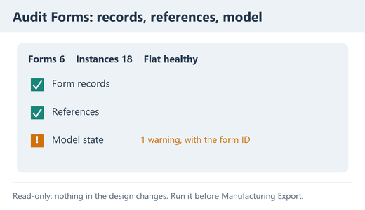
Audit Forms checks every form made with Create Form in the open design and changes nothing; it needs no license. Run it after you change the sheet and before Manufacturing Export.
It checks each form's record and model, the flat pattern, a curved form's datum point and the tool makers' limits (Checks: tool makers' limits), not Tab and Slot joints or the press-brake plan, which Bend Sheet checks itself.
| The report says | What it means |
|---|---|
| Definitions, Instances | The number of forms, and of copies in all their patterns. |
| Baseline flat pattern | The same note in every design: Manufacturing Export makes the clean native DXF. |
| ERROR flat.missing […]: Baseline flat pattern was deleted | A finding: its level, code, the form's ID (the last 8 characters name its timeline group, FW | Louver | 0327da7c) and the message. With none: No issues found. |
An ERROR stops Manufacturing Export, also a Reference-only
package. A WARNING does not: the tool makers' limits
(shop., catalog.) and tooling that is not
qualified (release.), which the export asks about. The
exception is a release. warning of an incomplete record
(…has no engineeringSnapshot…), which stops the export
too.
Most errors come from a change made after the forms: undo it, or open an earlier version of the design.
| Code | Means | What to do |
|---|---|---|
geometry.stale, geometry.owner_mismatch,
geometry.unhealthy | A feature of the form's timeline group was deleted or changed by hand, or fails. | Undo the change. |
flat.missing,
flat.recreated_after_forms | The flat pattern was deleted, or made again after the forms. | Undo the change. |
sheet.thickness_changed | The sheet is no longer the thickness the form was made for. | Undo the change. |
target.face_stale | The face under the form can no longer be found. | Undo the change. |
geometry.cross_form_footprint_collision | The tools of two forms overlap. | Move, resize or delete one with Edit existing form. |
pattern.derived_data_mismatch | The pattern no longer matches what was stored, for example a louver region whose sketches or neighbouring forms changed. | Rebuild it as the message says (Fill a louver region). |
release.engineering.snapshot_missing and other
release. warnings of an incomplete record | The form's record lacks its engineering data. | Delete the form and create it again. |
Manufacturing Export#
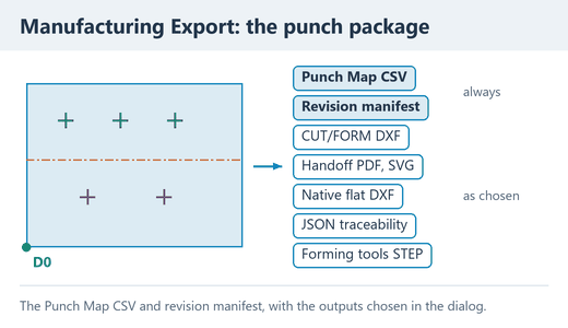
Manufacturing Export writes the forms made with Create Form as files for the shop: always the Punch Map CSV and a revision manifest, and the files you choose under Outputs.
With no such form in the design, Choose Output... stays greyed (This design has no form to export: add forms with Create Form first.); a part with bends only needs Bend Sheet's flat DXF (Outputs: PDF, DXF and CSV). The dialog opens with your last export's settings, except Reference-only package (not for manufacturing), chosen each time.
Export a punch-press job#
These steps write a production package for the punch press.
- Run Audit Forms and fix its errors.
- Open Manufacturing Export and set the Punch press group to how your shop runs the job; tick Show the job in 3D to step through the hits.
- Under Outputs, keep Same-datum CUT/FORM DXF + handoff PDF ticked; choose Forming tools (STEP) when a tool maker needs the punch and die solids.
- Click Choose Output.... The forms are checked: what stops the export is listed by form (The release was blocked before opening a file picker...), and tooling that is not qualified is asked about (Tooling that is not qualified, and Reference-only).
- Name the package (its Punch Map CSV); the name starts as the design's.
- Read the closing message: the files, the package revision, the face to
load up and the punch-press checks. Send the CUT/FORM DXF to the
cutting program and the handoff PDF to the punch press; keep every file
with its
.manifest.json.
The package#
The package is the set of files one export writes, each with the CSV's name, in its folder.
| File | What it holds | Written when |
|---|---|---|
Name.csv | The Punch Map, one row per instance (columns below). | Always |
Name.manifest.json | The package revision
(FWX-…, also on the sheets and in the DXF) and each
file's name and SHA-256 checksum, the STEP tools by name only: which
files belong together. | Always |
Name.json | Every form's IDs, sizes, places and tool evidence, and the handoff, for traceability and other software; the add-in does not read it back. | Machine-readable JSON traceability archive ticked; the handoff and Reference-only tick it |
Name.dxf | Fusion's own flat-pattern DXF, without the add-in's forms. | Clean native flat DXF ticked; never in Reference-only |
Name.svg | The shop sheet as an SVG. | Annotated blank handoff (SVG + datum schedule) ticked; the CUT/FORM DXF and per-face tools tick it |
Name_CUT_FORM.dxf | The cutting contours and forming marks for the punch-press program. | Same-datum CUT/FORM DXF + handoff PDF ticked; never in Reference-only |
Name_Handoff.pdf | The shop sheet for the operator. | Same-datum CUT/FORM DXF + handoff PDF ticked |
Name_Tools_per_tool.step,
Name_Tools_per_face.step | The punch and die solids (Forming tools (STEP)). | Forming tools (STEP) chosen; after the package |
A box another choice decides is greyed until nothing decides it, then gets your own setting back.
Clean native flat DXF keeps the features made before the forms, and later ones that do not depend on a form. If a later feature of yours would be lost or broken, nothing is exported and the design is put back (Clean flat export would remove or invalidate downstream features not made by this add-in...): place the cuts you need in the DXF before the forms in the timeline. A feature of a form that you suppressed yourself stays suppressed. If Fusion writes no DXF (Fusion did not write the native flat DXF ...), or the add-in cannot confirm that the model is back as it was, no package is written.
Several components with forms. The native flat DXF, the CUT/FORM DXF, the handoff sheets and the per-face tools need exactly one sheet-metal component with forms. Otherwise untick Clean native flat DXF and both handoff outputs, and set Forming tools (STEP) to None or One set per tool: the Punch Map and the JSON still list every form, measured on its own face.
| Punch Map columns | What they give |
|---|---|
form_id, punch_code,
tool_preset_id, instance_id | The form, its tool code, its library tool and the copy. |
handoff_number, handoff_x_mm,
handoff_y_mm, handoff_rotation_deg,
handoff_loaded_up, handoff_form_loaded,
handoff_height_mm, handoff_hit_order,
handoff_station | With the annotated handoff: the
form's number, X, Y and angle from D0, the face up, the form as loaded
(up, down or cut), its height,
hit and station. |
x_mm, y_mm,
rotation_deg | On the face the form was placed on, not in any DXF. |
release_status, tooling_qualified,
qualification_findings | The release and the tool's qualification, then the tool's evidence. |
form_direction, form_height_mm,
height_datum, made_by,
louver_ends, progressive_hits,
thread, knockout_trade_size,
path_segments, do_not_mirror,
shop_checks | For the shop: out of or into the face, the height and its datum, how the form is made, a bead's path as lines and arcs (with its length and smallest radius), the tool makers' limits found. |
dim_… | One column per size. |
Replacing a package. When files of the package exist, the export
lists them and Yes replaces them all together. A file of an older
package under that name that this export would not write, such as
Name.dxf after you untick Clean native flat DXF, stops
it (An older companion would be left beside the new revision:
...): choose another name, tick that output again, or move the file
out of the folder.
Tooling that is not qualified, and Reference-only#
A production export warns about forms whose tooling is not qualified; a Reference-only package is for review.
Before it asks for a file name, a production export lists the forms whose tooling is not qualified, by form type and count with the reasons (The tooling of these forms is not qualified for production: ...), and asks whether to export anyway.
- Yes writes the package with those forms marked: in the Punch
Map's
tooling_qualifiedandqualification_findings, the JSON, the CUT/FORM DXF header, the manifest'stoolingNotQualifiedlist and the closing message, and on the handoff sheets by an amber Production release, tooling not qualified label and a Tooling not qualified note on each such form. Check them against the real tools before manufacturing. - No writes nothing.
A form keeps the tool evidence it was made with, also through Edit existing form. Only a form made with a Shop qualified tool chosen in the Tool list of Create Form, and not changed since, clears the warning: a Vendor specified tool still asks for a shop trial, and evidence typed into the Engineering qualification group without a library tool is bound to no tool (Engineering qualification). To clear it:
- In Create Form, choose Edit existing form, select the form, tick Delete this form, click OK and answer Yes.
- Create the form again with a Shop qualified tool from the Tool list, its Actual workpiece and press setup checked.
Reference-only package (not for manufacturing) makes a package for review:
- It always writes the JSON and never a cutting DXF, neither the native flat DXF nor the CUT/FORM DXF; the SVG and the handoff PDF only while their boxes are ticked.
- Every file is marked
UNVERIFIED_DO_NOT_MANUFACTURE; the sheets say Reference only — do not manufacture. - Tooling that is not qualified is not asked about.
- Audit Forms errors and incomplete records stop it, and so does a blank that cannot be mapped while the handoff outputs are ticked: untick them.
Punch press#
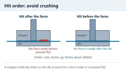
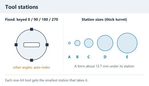
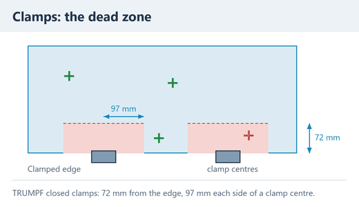
The Punch press group sets how the shop runs the job; the handoff
sheets, the CUT/FORM DXF and the CSV's handoff_ columns
follow it.
Its settings are greyed while Annotated blank handoff (SVG + datum schedule) is unticked. Its checks are warnings, listed in the handoff PDF and SVG (the CSV adds each form's station and checks); the export never stops on them. For +N and D0, see The handoff sheets and the CUT/FORM DXF.
| Setting | What it does |
|---|---|
| Load the blank | Top face (+N) up, Top face (+N) down, or Auto: most forms up, the face that makes most forms UP. Each form is then UP or DOWN as loaded, with its height; a knockout is cut in place. |
| Tool stations | Auto-index (any angle), or Fixed, keyed 0 / 90 / 180 / 270, which marks every form at another angle for an auto-index station (round dimples and extruded holes never need one). |
| Station sizes | Thick turret, stations A to E, Thick turret with an F station, TRUMPF tool sizes 0 to 2 or TRUMPF with size 5 tools. Each one-hit tool gets the smallest station that takes it: on a thick turret (Mate Ultra TEC sizes) a form is about 12.7 mm smaller than its station, from station B, an extruded hole from C, a knockout by the AMADA table; a TRUMPF station takes a tool of its full size. A tool too large for every station is flagged, unless it steps along a bead path. |
| Hit order | Avoid crushing where possible also moves a hit before a form its tools would press flat (below), within the forms up and within the forms down, where such an order exists. Plan order: cuts, forms up, forms down keeps the plan's order. |
| Clamped edge | The edge of the blank, as loaded, that the clamps hold: Lower edge (Y = 0, at D0), Upper edge, Left edge (X = 0) or Right edge. |
| Clamp dead zone | How far from that edge no tool can punch with the clamps closed (72 mm for TRUMPF closed clamps); forms in it are flagged. |
| Clamp centres (mm) | Empty: the whole edge counts as
clamped. Or where the clamps sit along the edge, in mm from D0
(300, 900): Dead zone each side of a clamp appears
(97 mm for TRUMPF), and only forms that close to a clamp centre are
flagged. |
The plan punches the cuts first, then the forms up, then the forms down, one tool at a time in one direction (AMADA), louvers from their open side toward their root (Conic). Forms made in a press-brake die come last; the sheets say press brake instead of a hit number.
A stripper holds the sheet on the die through every stroke (Mate, TRUMPF): a form made UP under a later hit's stripper, or DOWN over a later hit's die, is pressed flat. The check flags such hits, taking the tools as discs the size of their station's stripper and die; when no order avoids them, it says to relieve the tool or space the forms.
A value the job cannot use greys Choose Output... and says why
above it: a length that is negative or not a length, or clamp centres in
another unit or such as 1,200, which reads two ways (type
300, 900: a space after each comma, a point in a
decimal).
Show the job in 3D draws the blank as loaded, without adding anything to the design: the forms made before the hit, the hit's tool between its station's stripper and die, the forms to come as outlines, and the clamps with their dead zone. Hit steps through the hits; Stroke (%) moves the tool from open (0 %) to the bottom of its stroke (100 %).
The text under them describes the hit, its setup and its checks, CHECK lines in red; a tool that lands on a form turns red with it. The camera comes back when you switch the view off or close the dialog.
The handoff sheets and the CUT/FORM DXF#
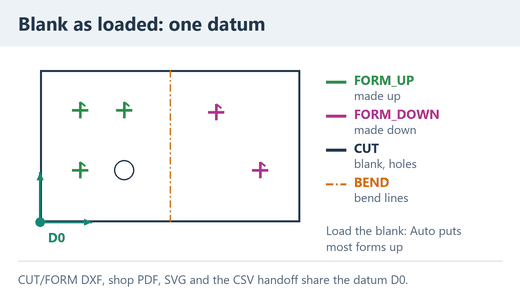
The handoff sheets and the CUT/FORM DXF show the blank and its forms for the punch press, all measured from one datum.
Annotated blank handoff (SVG + datum schedule) and Same-datum
CUT/FORM DXF + handoff PDF, ticked at first, write them; with the
CSV's handoff_ columns they share the datum, in millimetres,
under one package revision. Fusion's native flat DXF keeps its own origin
and orientation: register the two before you combine their
coordinates.
- +N is the face the sheets call the top: on a flat blank, the face the first form was placed on; on a folded part, the top face of Fusion's flat pattern. -N is the other face.
- D0 is the datum corner, the lower-left corner of the blank's
outline as the sheets show it. X and Y are measured from it
(
FW-BLANK-XY), angles counterclockwise from +X; the sheets' notes give D0 and the axes in component coordinates. - Everything is drawn from above as loaded: with +N down the sheets show the -N face, turned over left to right (X from the other edge, angles 180° minus the model's). The sheets say not to mirror the blank: the forms are directional.
What they map. One sheet-metal component: a flat blank (one flat sheet of even thickness, square-cut), or the flat flanges of a folded part with a healthy native flat pattern, where temporary marks, removed before anything is written, place each form to 0.005 mm. The bend allowances are Fusion's; no forming strain is calculated. All copies of one form must sit on one flat flange, each tool footprint clear of bends, edges and holes: use a separate form on each flange.
Forms on curved faces, a blank of another shape or a flange that cannot be measured stop the export (The annotated blank handoff could not be made: ...); nothing is guessed. To export without the handoff, untick both outputs and set Forming tools (STEP) to None or One set per tool. These checks are geometric: they do not qualify the forming process.
The CUT/FORM DXF is R12, in millimetres in every design. Its header names the package revision, the face to load up and any forms whose tooling is not qualified.
| Layer | What it holds |
|---|---|
CUT | The only cutting layer: the blank outline, its holes (Tab and Slot cuts too), the pre-holes of extruded holes and the slits of louvers formed in a press-brake die (cut first, formed after). Circles and arcs stay true; other curves become chords within the tolerance the sheets give. |
FORM_UP, FORM_DOWN | A cross at each tool centre and a heading mark for the forms made up or down as loaded, and a bead's path. |
FORM | The same for knockouts, which are cut in place. |
NOTES | Each form's number, its tool code, UP or
DOWN with its height, and its hit (#3) or PRESS
BRAKE. |
BEND | The bend lines of a folded part's native flat, CENTER line type. |
BEND or the forming
marks to the cutter: the marks locate operations, they are not die
geometry or stretched material.The handoff PDF has the bend sheet's layout:
- the part block: blank size, thickness, forms and tools, the face to load up, the view, the datum, the package revision and the release status;
- the blank: cutting contours, dash-dot bend lines, D0, and each form's footprint and number in its layer's colour (green made up, magenta made down, red cut in place);
- the forming schedule in hit order, the punch-press checks and the datum notes.
Use the coordinates, not the printed scale: the drawing is fitted to the page. The SVG is the same sheet with its pages one under another; each schedule row is a group carrying its instance ID, and the whole handoff is in its metadata.
Forming tools (STEP)#
Forming tools (STEP) writes the punch and die of the forms as solids, for a tool maker to start the stamping tool from: the tools that Show the forming tool draws, at the bottom of the stroke, the die on the sheet and the punch at the form's inside crown.
| Option | What it writes |
|---|---|
| None | No tools. |
| One set per tool | Each tool once (per tool code and size), in the form's own frame, centred on the form, made up: the die above the sheet, the punch below; a knockout punched from above. |
| One set per face | Every form of one flat face of the
blank, in its place, as one die set: an upper block on the sheet's top
face and a lower one under it, each with its dies' cavities and holes cut
in and its punches standing out. The sets are in the blank's datum as
loaded (FW-BLANK-XY, the sheet
from Z 0 to its thickness, the blank's outline as a sketch), in line with
the CUT/FORM DXF and the handoff PDF. A dedicated die makes a progressive
louver whole, in one hit. |
| Per tool and per face | Both. |
The tools are built after the package and stay open in a new, unsaved design named after yours (… - forming tools; save it to keep a Fusion copy). The STEP files go beside the package, replacing older ones of those names; one message lists the package and the tools. When Fusion does not write one (another program holds the old file open, say), the message names it (Fusion did not write ...) and the files written before it.
Beads along a path, gussets across a bend and forms on curved faces are left out with a note; with no tool left, the package is written alone. Only the forming shapes are drawn: add the holders, strippers, springs and fixing before use.
Enclosure example#
An enclosure with louvers and tapped collars, from the model to the shop:
- Build it as one sheet-metal body with Fusion's base and flange tools, add its cut-outs, and close its open corners with Tab and Slot joints.
- Add a louver with Create Form, repeated by a Rectangular pattern or a Louver region, and extruded holes with the thread and tap of the collars (Form types and sizes).
- Run Audit Forms, Manufacturing Export and Bend Sheet as in Parts with forms and bends: cut the blank from the CUT/FORM DXF, never from the bend sheet's flat DXF.
- Make a Fusion drawing for the assembly views, dimensions and notes.
Good practice#
These habits keep the forms editable and Audit Forms free of errors.
- Change a form only with Edit existing form, never a feature of its timeline group by hand.
- Keep the flat pattern the forms were made on: do not delete it or make a new one after the forms.
- On a cylinder, leave the vertex or point you picked under Curved coordinate-zero reference where it is.
- Fix Audit Forms errors before you add more forms: Create Form refuses a new form while another form of the component is damaged or has lost its sheet body.
License and trial#
Every command except Audit Forms and About Sheet Metal and Press Brake needs a license for the Autodesk account signed in to Fusion. One license covers the Windows and the macOS build.
Free trial, one per Autodesk account:
- Sign in to Autodesk, go online and open one of those commands. The first time, it does not open: Sheet Metal & Press Brake is checking your license in the background.
- Open it again after a few seconds (the message can come once more), until 3-day trial active until gives the date and time the trial ends.
- Open the command again to use it.
Opening About does not start the trial; Check license now does.
Buy a yearly or monthly subscription (About shows the price) for the Autodesk account you sign in to Fusion with, in one of two ways:
- On the Autodesk App Store: subscribe on the Sheet Metal and Press Brake listing (Windows; its subscriptions need PayPal). Its installer installs the Windows build.
- By card on the product page (Open product page in About): pay with the email address of your Autodesk account; the license goes to that account.
Either one unlocks the Windows and the macOS build. Then click Check license now in About: the License box shows Access granted.
Activation code from VanThanBK: signed in and online, type it under Activation code in About and click Apply (the dialog's OK). The message says Sheet Metal & Press Brake was activated successfully. or why not, such as The activation code is invalid or expired. A code belongs to the first Autodesk account that uses it (This activation code is already assigned to another account.).
- Check license now asks the license server again, at most once a minute (A license check is already running or was requested less than one minute ago.). While this computer has no saved license for the account, About shows Not activated after Fusion starts until a command or this button has checked it.
- Offline, the add-in uses the license it saved on this computer for the same Autodesk account for up to 7 days; About adds (offline cache) to the state. A trial still ends on its date.
- Another Autodesk account signed in to Fusion: the commands wait until its license has been checked; open the command again after a few seconds.
| The command says | What to do |
|---|---|
| ... is checking your license in the background ... | Open the command again after a few seconds. If it keeps coming, the License box in About says what is missing, such as Sign in to Autodesk and connect to the internet or License server unavailable. |
| ... trial has expired. (also when a bought license or a code has ended) | Buy, or enter a code. Bought or renewed already: click Check license now in About. |
| This ... command requires a license. | The account has no valid license: buy, or enter a code. |
| Sign in to Autodesk, connect to the internet, and try this ... command again. | Sign in to your Autodesk account in Fusion and go online. |
| ... could not reach the license service and no current signed offline grant is available. | No license was saved in the last 7 days: go online and open the command again. |
| Commercial licensing is not configured in this ... build. | Install the release from the product page, or write to support. |
| ... No design changes were made. Open About ... to check or activate the license. | The license ended or the account changed while the dialog was open: the command stopped before it changed the design or wrote a file. Check the license in About. |
About, updates and your data#
About Sheet Metal and Press Brake shows the version, the license and the updates; opening it needs no license.
| Box or button | What it does |
|---|---|
| About | The version, the price and what the commands do. |
| License | The state (such as 3-day trial active, Access granted, Activated with code, Trial expired), the date it is valid until, and the Autodesk account, user ID and App ID it is checked for. |
| Updates | Whether a newer version is published (below). |
| Activation code, Apply, Check license now | See License and trial. |
| Check for updates | Looks for a newer version again. |
| Download latest version | Shown when a newer version is published: opens its download in your web browser. |
| Open product page, Open help, Open privacy policy | The product page, this guide or the privacy policy, in your web browser. |
| Privacy | License checks use your Autodesk account ID and email; looking for updates sends only the App ID and the platform; a download request sends your account details, and the server records it. Design content is not sent. |
Updates. The first time you open About after Fusion starts, it looks for a newer version. The Updates box then says You have the latest published version (...), or Version ... is available. with what is new. The download needs your Autodesk sign-in and a bought license or an activation code; during a trial it says Downloads require an active license for this product. ...
To install a new version, follow Update in the installation guide (Windows, macOS):
- In Utilities > Add-Ins > Scripts and Add-Ins, select the add-in, untick Run on Startup and click Stop.
- Quit Fusion.
- Delete the old add-in folder and unzip the new one in the same place, with the same name.
- Start Fusion, run the add-in if it is not running, tick Run on Startup and check the version in About.
Stop and Run alone keep the old version loaded. On macOS, allow the add-in again if macOS asks, as the guide shows.
Your data stays outside the add-in folder, so updating or deleting
the add-in keeps it: in
%APPDATA%\VanThanBK\SheetMetalPressBrake on Windows,
~/Library/Application Support/VanThanBK/SheetMetalPressBrake
on macOS.
| File | What it holds |
|---|---|
press-brake-library.json | The Press Brake Library, with the test-bend calibrations. |
tool-library.json | The Forming Tool Library. |
settings.json | What the dialogs remember, such as the press-brake setup last used and the sizes of each form type. |
license folder | The license as last checked. |
To back up a library or move it to another computer, export it: Export the library (JSON) in Press Brake Library (Import, export and the library file) and Export library JSON... in Forming Tool Library. Those sections also say what happens when a file cannot be read.
Words used in this guide#
The words this guide uses, each with the section that explains it.
| Word | Meaning |
|---|---|
| t, V, Ri | The sheet thickness, the die's V opening and a bend's inside radius (Apply Bend Rule). |
| K-factor | Where the line that keeps its length through a bend lies, as a share of t from the inside face; 0.5 is the middle (Apply Bend Rule). |
| Bend allowance (BA) | That line's length through the bend (Apply Bend Rule). |
| Bend deduction (BD) | How much shorter the flat is than the outside flange lengths added (Apply Bend Rule). |
| Bend rule | The part's Fusion sheet-metal rule: thickness, bend radius and K-factor (Apply Bend Rule). |
| Bend, step | B1, B2… are the bends of the flat; a step is one hit, one row of the bend order (The bend table). |
| UP, DOWN | UP folds the flange toward the flat's top face, DOWN away from it (The bend table). |
| X, Gauge | A step's back gauge distance from the bend line, and what rests against the gauge (Back gauge). |
| Tooling system | The clamp a machine has and its tools fit, such as European (Promecam) or New Standard (Tooling systems). |
| Station | Press brake: the pieces set along a bend for one step; punch press: a tool place in the turret (Punch press). |
| Sectioned set, horn | The pieces of a punch or die your shop has; a horn is an end piece relieved for a formed wall (Tool length: one piece or a sectioned set). |
| I have this tool | The tick on a tool your shop has; once a die you bend with that fits the machine is ticked, the die lists, the suggested die and Auto use only the ticked dies (punches the same way); hemming, flattening and offset tools are ticked apart, so with only those ticked every tool you bend with is still used (The tools you have). |
| Section check | The part's cross-section moved through each step against the tool outlines (How the section check works). |
| 3D check | The real part folded step by step against the tools as solids (3D check). |
| ERROR, CHECK | What the plan cannot make as it is; a risk to look at (Checks). |
| Not checked, Assumed | The checks a missing library value stops; the values and outlines taken because the library has none (Checks). |
| Form, instance | What one Create Form makes, with its pattern; each copy in the pattern (Create Form). |
| Punch Map | The CSV Manufacturing Export always writes, one row per instance (The package). |
| Handoff, D0, +N | The shop PDF, SVG and CUT/FORM DXF of the blank as loaded on the punch press; D0 is its datum corner at the lower left, +N its top face and -N the other (The handoff sheets and the CUT/FORM DXF). |
| Evidence | What a forming tool's data rests on: Unverified / reference, Vendor specified or Shop qualified (Engineering qualification). |
If something goes wrong#
What to do when a command does not open, the commands are missing or a problem stays.
| Problem | What to do |
|---|---|
| A command does not open: Sheet Metal & Press Brake command start or ... run (the add-in could not load), or ... could not start. Restart Fusion and try again, ... | Quit Fusion, start it again and try once more. |
| The commands are missing | When Fusion cannot add the Press Brake panel, they are in the Add-Ins panel of the Utilities tab. In neither, check in Utilities > Add-Ins > Scripts and Add-Ins that the add-in runs; Fix a problem in the installation guide helps when it does not. |
| A license message | License and trial. |
| A command refuses | Its message says why; the command's section explains it. |
| The problem stays | Write to support@vanthanbk.com with the message (copied, or a screenshot), your Fusion version, the add-in version from About and, if you can, the design. |
Support: support@vanthanbk.com
Product: vanthanbk.com/company/sheet-metal-press-brake
Installation: vanthanbk.com/docs/installation
Privacy: vanthanbk.com/privacy